Paper box rapid gluing and forming machine

A glue forming machine and fast technology, applied in papermaking, paper/cardboard containers, container manufacturing machinery, etc., can solve the problem of slow glue application, and achieve the effect of reducing labor intensity, fast speed and high efficiency

Active Publication Date: 2020-07-28
湖南中南金叶印务有限责任公司
View PDF10 Cites 0 Cited by
  • Summary
  • Abstract
  • Description
  • Claims
  • Application Information

AI Technical Summary

Problems solved by technology

[0002] When making various packaging cartons, it is often necessary to glue the flip cover at the bottom of the carton. When glue is used for gluing, manual gluing is often used now, and manual gluing often has the defect of slow gluing speed, so There is an urgent need for a gluing equipment to replace manual gluing to speed up gluing and reduce the labor intensity of workers

Method used


Image

  • Paper box rapid gluing and forming machine
  • Paper box rapid gluing and forming machine
  • Paper box rapid gluing and forming machine

Examples


Embodiment 1

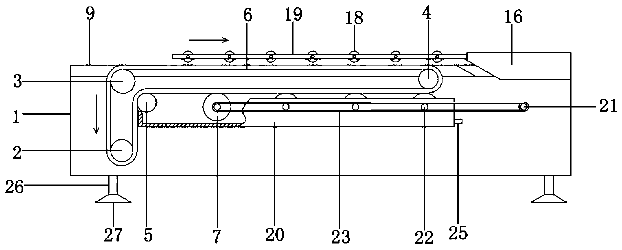
[0027] Such as Figure 1 to Figure 4 As shown, a carton 28 fast gluing forming machine includes a casing 1, a gluing mechanism and a chain rail transmission mechanism, and the gluing mechanism includes a driving wheel 2, a first track changing wheel 3, and a second track changing wheel 4. The third track-changing wheel 5, the coating belt 6 and several glue-coating wheels 7, the driving wheel 2 is connected with the transmission shaft of the first motor 8 arranged in the casing 1, and the first track-changing wheel 3. The second track changing wheel 4, the third track changing wheel 5 and the glue coating wheel 7 are arranged on the outer wall of the casing 1, the first track changing wheel 3 is located directly above the driving wheel 2, and the second track changing wheel 4 At the same horizontal position as the first track changing wheel 3, the third track changing wheel 5 is located below the first track changing wheel 3 and the second track changing wheel 4, and the coate...

Embodiment 2

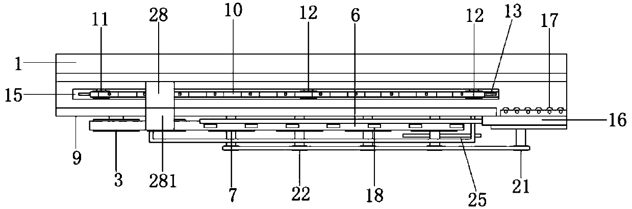
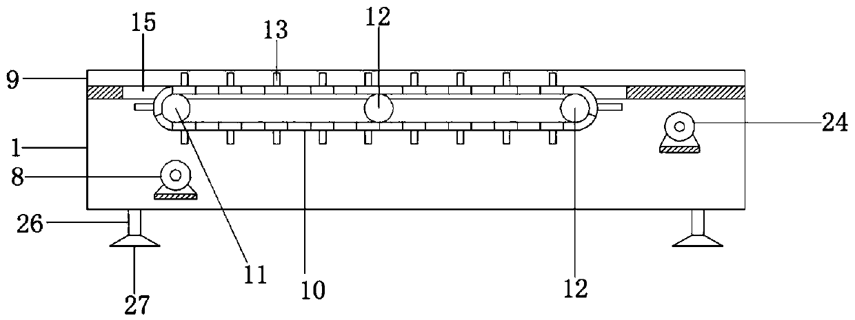
[0031] On the basis of Example 1, such as figure 1 , figure 2 with image 3 As shown, the chain rail transmission mechanism includes a guide rail plate 9, a transmission chain 10, a driving gear 11, several driven gears 12, a vertical baffle plate 13 and a second motor, and the guide rail plate 9 is arranged in parallel with two On the casing 1, the casing 1 between the guide rail plates 9 is provided with a through groove 15, and the driving gear 11 and the driven gear 12 are respectively arranged on the first rotating roller and the second rotating roller, and are located in the through groove 15 Between, one end of the first rotating roller is connected to the transmission shaft of the second motor, and the other end is connected to the inner wall of the casing 1, the second motor is arranged in the casing (not shown in the drawings), and the first The two ends of the two rotating rollers are rotatably connected with the inner wall. The transmission chain is connected to...

Embodiment 3

[0033] On the basis of Example 1, such as figure 2As shown, the inner wall of the bending plate 16 is rotatably provided with tightening rollers 17, several in number, which just accept the end of the through groove 15, and the inner side of the tightening rollers 17 is in the same horizontal direction as the inner wall of the guide rail plate 9 in the horizontal direction. . After the carton 28 is transported to the end of the through groove 15, it is pushed to the take-up roller 17 by the carton 28 transported from the back. Because there is a certain distance between the cartons 28 that are glued before and after, there is also a certain time difference, so The carton 28 located at the tightening roller 17 will stay for a period of time, and the inner side of the tightening roller 17 is in the same horizontal direction as the inner wall of the guide rail plate 9 in the horizontal direction, and the distance between the guide rail plates 9 must be equal to the carton 28 whe...


PUM


Abstract

The invention relates to a paper box rapid gluing and forming machine. The paper box rapid gluing and forming machine comprises a machine shell, a gluing mechanism and a caterpillar track conveying mechanism, wherein the gluing mechanism comprises a driving wheel, a first track transfer wheel, a second track transfer wheel, a third track transfer wheel, a gluing belt and a plurality of gluing wheels, the driving wheel is connected with a transmission shaft of a first motor arranged in the machine shell, the first track transfer wheel, the second track transfer wheel, the third track transfer wheel and the gluing wheels are arranged on the outer wall of the machine shell, the first track transfer wheel is located over the driving wheel, the second track transfer wheel and the first track transfer wheel are located at the same horizontal position, the third track transfer wheel is located below the first track transfer wheel and the second track transfer wheel, and the gluing belt is connected with the driving wheel, the first track transfer wheel and the second track transfer wheel in a wrapping manner and bypasses the third track transfer wheel from top. The provided paper box rapid gluing and forming machine can replace manual gluing of paper boxes, the gluing speed is higher, and the labor intensity of workers can be reduced.

Description

technical field [0001] The invention relates to the technical field of coding equipment, in particular to a carton rapid gluing forming machine. Background technique [0002] When making various packaging cartons, it is often necessary to glue the flip cover at the bottom of the carton. When glue is used for gluing, manual gluing is often used now, and manual gluing often has the defect of slow gluing speed, so There is an urgent need for a gluing equipment to replace manual gluing to speed up gluing and reduce the labor intensity of workers. Contents of the invention [0003] The purpose of the present invention is to improve and innovate on the shortcomings and problems existing in the background technology, and to provide a carton rapid gluing molding that can replace the manual gluing of cartons, has faster gluing speed, and can reduce the labor intensity of workers. machine. [0004] The technical solution of the present invention is to construct a carton rapid glui...

Claims


Application Information

Patent Timeline
Patent Type & Authority Applications(China)
IPC IPC(8): B31B50/62B31B50/04
CPCB31B50/62B31B50/042
Inventor 杨年炯
Owner 湖南中南金叶印务有限责任公司
Why Eureka
Try Eureka