RFID tag

Inactive Publication Date: 2007-02-22
FUJITSU FRONTECH LTD
View PDF8 Cites 203 Cited by
  • Summary
  • Abstract
  • Description
  • Claims
  • Application Information

AI Technical Summary

Benefits of technology

[0007] It is an object of the present invention to at l

Problems solved by technology

However, the above technology of manufacturing an RFID tag is not cost-effective because,

Method used


Image

  • RFID tag
  • RFID tag
  • RFID tag

Examples


first embodiment

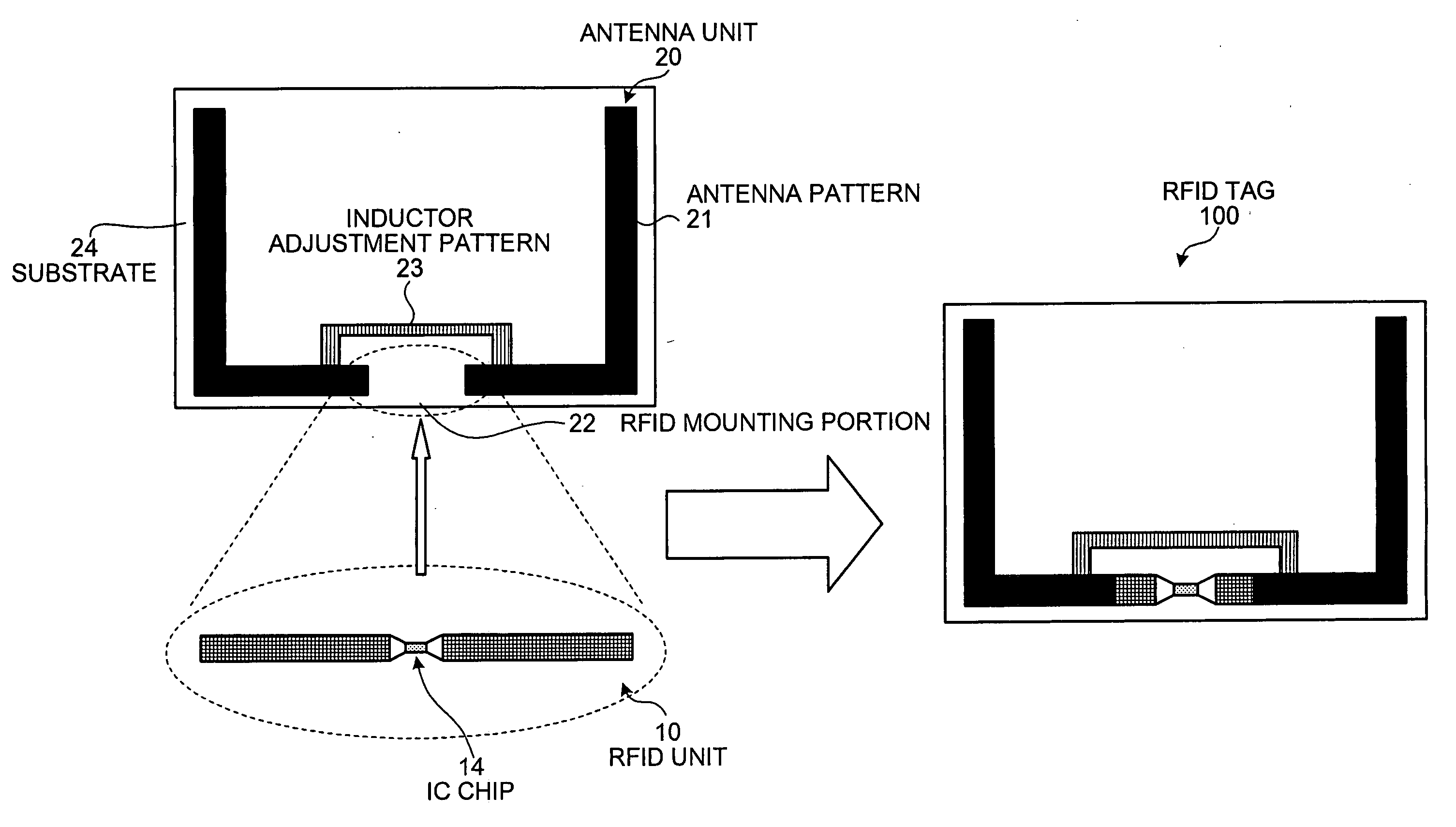
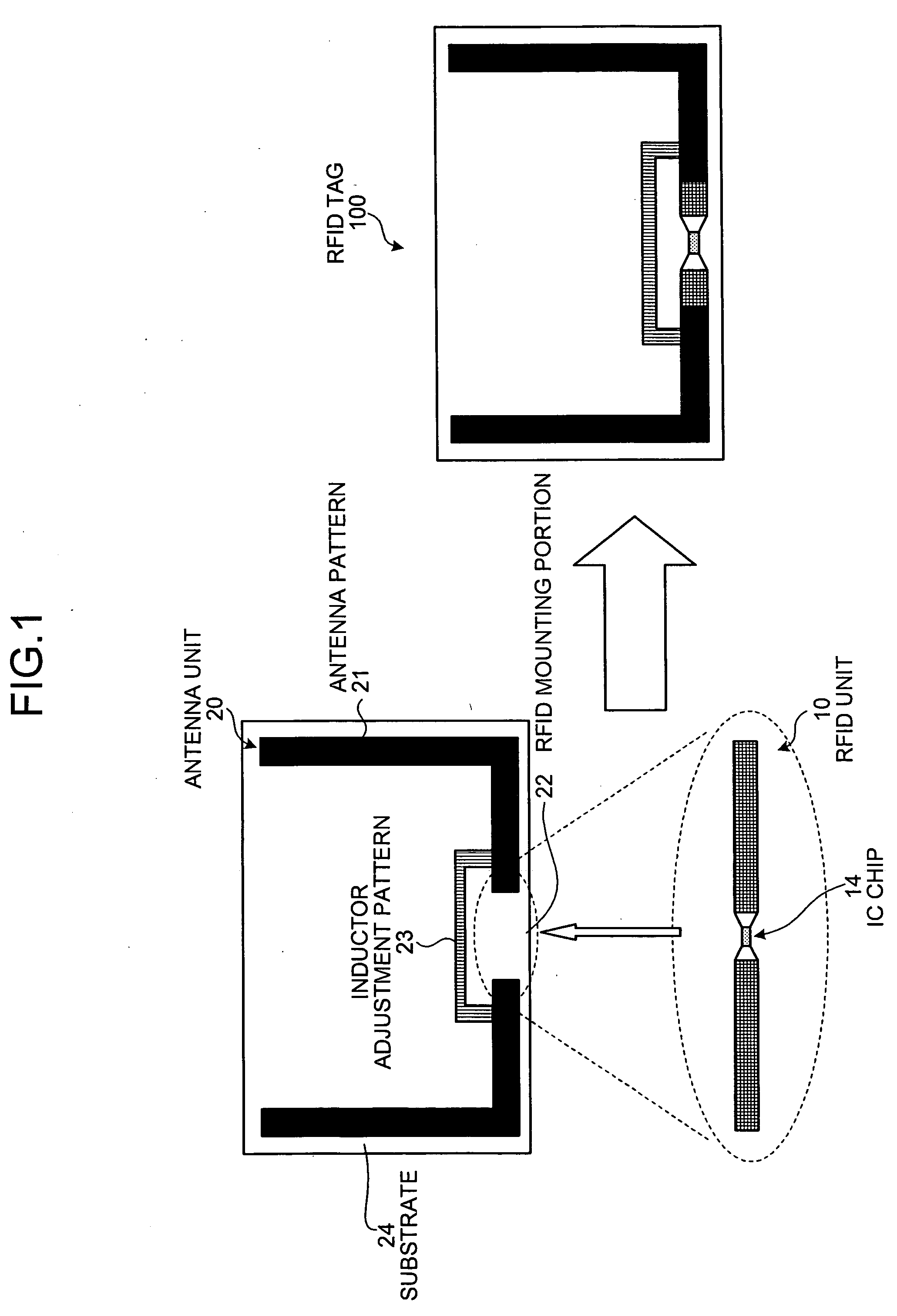
[0017]FIG. 1 is a schematic of an RFID tag according to the present invention. As shown in FIG. 1, an RFID tag 100 includes an IC chip unit including an IC chip and an antenna unit including an antenna pattern. The main feature of the RFID tag 100 is that lengths of the IC chip unit and an RFID mounting portion in which the IC chip unit is mounted are standardized to a common length. With such structure, the IC chip units and the antenna unit can be mass-produced independently, thereby reducing manufacturing cost.

[0018] As shown in FIG. 1, an RFID unit 10 that includes an IC chip 14 has a pattern of a minute dipole antenna. A length of the RFID unit 10 is standardized to a predetermined length. Therefore, it can be manufactured independently of an antenna unit 20, irrespective of the material to which the RFID tag 100 is to be attached. The antenna unit 20 includes an antenna pattern 21, an RFID mounting portion 22, and an inductor adjustment pattern 23. A length of the RFID mountin...

second embodiment

[0043] Thus, the inductor mounting portion 42 is provided in the antenna unit 40 for mounting the inductor unit 30. Consequently, the inductor unit 30 can be mounted after the antenna unit 40 is manufactured, and before the RFID unit 50 is mounted to the antenna unit 40. Therefore, it is possible to make the inductor unit 30 to be mounted suitable, in advance, for the dielectric constant of the material to which the RFID tag 200 is to be attached or to the impedance of the antenna unit 40. Thus, it is possible to manufacture the RFID tag 200 having an optimal coordination.

[0044] The present invention is not limited to the embodiments described above, and various modifications may be applied.

[0045] While in the embodiments, the length of the RFID unit is made to be suitable for transmitting and receiving radio waves having the shortest wavelength, the length of the RFID unit may be any length.

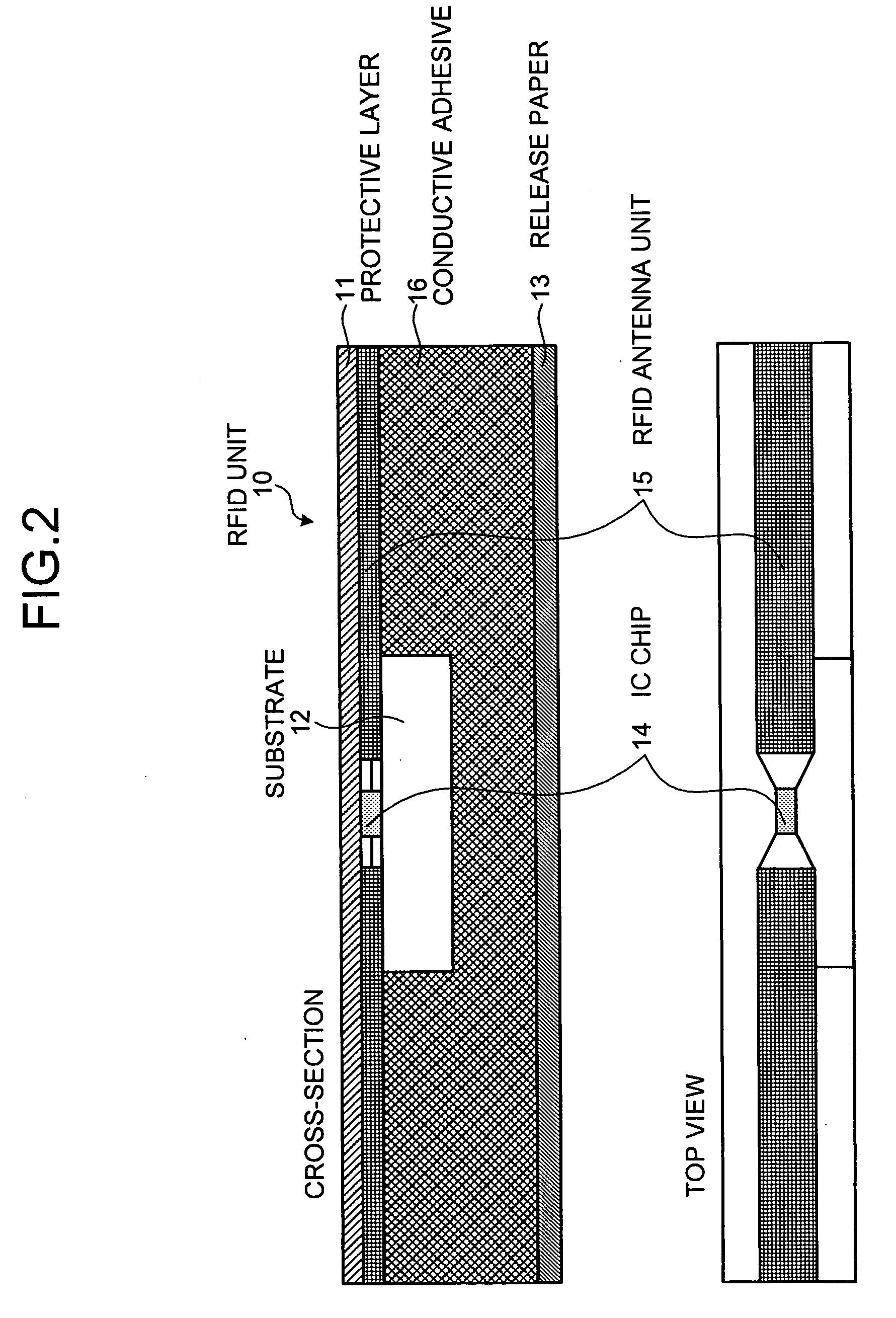
[0046] While in the above embodiments, a conductive adhesive is provided on the RFID unit...


PUM

PropertyMeasurementUnit
Lengthaaaaaaaaaa
Electrical conductoraaaaaaaaaa

Abstract

An RFID tag includes an RFID unit and an antenna unit. The RFID unit is formed in a form of a minute dipole antenna having a predetermined length and includes an IC chip. The antenna unit includes an antenna pattern and an RFID mounting portion. Lengths of the RFID unit and the antenna unit are substantially identical. The RFID unit and the antenna can be manufactured independently.

Description

BACKGROUND OF THE INVENTION [0001] 1. Field of the Invention [0002] The present invention relates to a radio frequency identification (RFID) tag. [0003] 2. Description of the Related Art [0004] In an identification technology for products, an RFID has come to be used in place of a barcode. The RFID is the technology that allows reading and writing of data from or into an RFID tag in a non-contact manner. The data is read and written by an RFID reader / writer. The RFID tag includes an integrated circuit (IC) chip, an antenna, and a substrate. The IC chip stores data such as its own identification code, and performs data exchange via the antenna with the RFID reader / writer. The IC chip is mounted on the antenna. [0005] An internal layout of the RFID tag varies depending on a material to which the RFID tag is to be attached. In other words, an antenna pattern and a position of the IC chip on the antenna depend on the material. Therefore, in manufacturing the RFID tag, a manufacturing ap...

Claims


Application Information

Patent Timeline
IPC IPC(8): G06K7/00G08B13/14
CPCY10T29/49124G06K19/07749
Inventor KAWAMATA, HIROSHI
Owner FUJITSU FRONTECH LTD
Why Eureka
Try Eureka