Method and a device for removing vehicle windows

a vehicle and window technology, applied in the field of vehicle fixed window elements, can solve the problems of reducing the service life of the vehicle, the risk of destroying both the actual window element and the interior or exterior parts of the vehicle, and the cleaning and additional cost of a new window element, so as to achieve secure and effective non-destructive removal and minimal operation.

Inactive Publication Date: 2007-02-22
RAMHUSET PATENT AB
View PDF12 Cites 25 Cited by
  • Summary
  • Abstract
  • Description
  • Claims
  • Application Information

AI Technical Summary

Benefits of technology

[0006] It is a basic object of the invention to provide an improved method for the non-destructive removal of a fixed window element from a vehicle, which method may be performed on small side window elements.
[0008] It is a further object of the invention to provide a method for the non-destructive removal of a window element from a vehicle by which a fixed side window element may be easily removed with a minimum of operations.
[0009] Briefly, the invention provides a method for removing fixed vehicle windows using a cutting wire that is threaded through the window element adhesive and that is placed in a loop around the perimeter of the window element. According to the invention a first end of the cutting wire is attached to a first wire wind-up means of a single tool and a second end of said cutting wire is attached to a second wire wind-up means of said single tool. The first and second ends of the wire are then pulled with the first and second wire wind-up means until the wire cuts through the adhesive around the entire perimeter of the side window element. The suggested method is very compact both with regard to the actual space occupied by the single two-winch tool and with regard to the operation thereof. Therefore, said method provides a unique possibility for secure and effective non-destructive removal of smaller-sized fixed side windows from vehicles.

Problems solved by technology

All of the described methods are comparatively time-consuming and cumbersome and involve an apparent risk of damaging both the actual window element and interior or exterior parts of the vehicle.
In such situations, it has up to the present day been common practice to crush the window element, with the resulting cleaning and additional cost of a new window element.
The only remaining options are to use one of the above described time-consuming, cumbersome and possibly damaging methods employing a knife or a manually operated wire.
Additionally, such methods often cause damages also to the actual window element, so that the window element will have to be replaced anyway.

Method used


Image

  • Method and a device for removing vehicle windows
  • Method and a device for removing vehicle windows
  • Method and a device for removing vehicle windows

Examples


Embodiment Construction

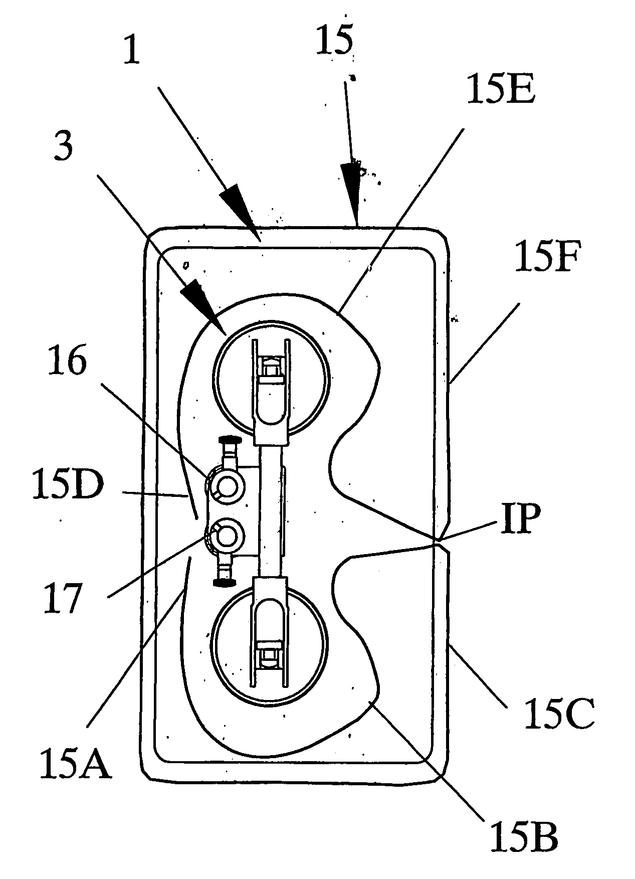
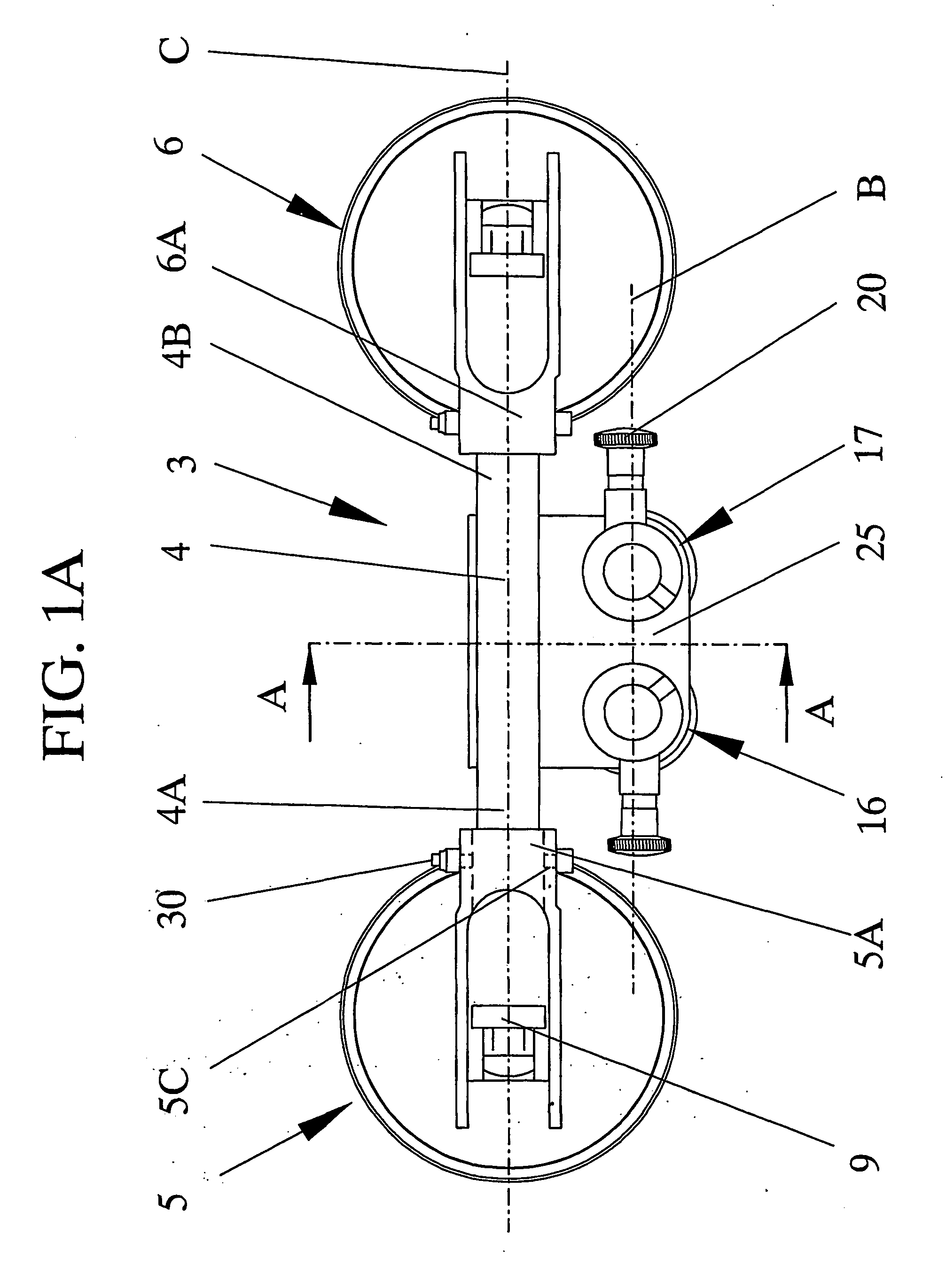
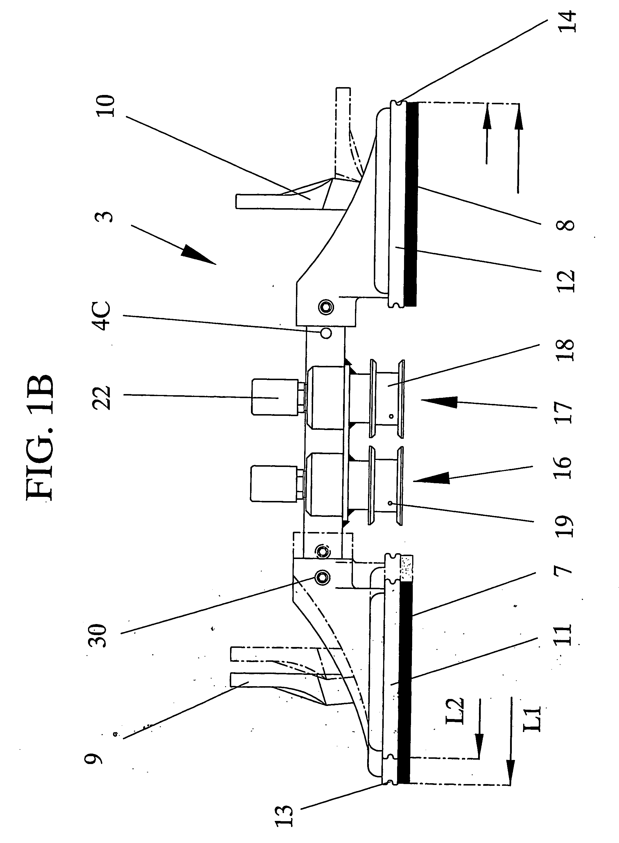
[0019] An exemplary illustrative embodiment of the tool 3 according to the invention is illustrated in FIGS. 1A, 1B and 1C. The basic design of this tool 3 is based on that of a hand tool that is presently used in the inventors own system “Roll out 2000®” that is employed for cutting the sealant / adhesive bonding a vehicle windshield to the vehicle body and thus for removing such a windshield. In said basic design the tool 3 has an elongate handle 4 with two suction members 5, 6 that are attached to each end section 4A, 4B of the handle 4, preferably by means of bolts 30 and nuts 31. The bolts are extended through holes, only one hole 5C indicated to the left in FIG. 1A, in support portions 5A, 6A of the respective suction members 5, 6 and through bores 4C in the respective end regions 4A, 4B of the handle.

[0020] In the illustrated embodiment of the invention the mutual distance between the suction members 5, 6 and thereby the overall length L1, L2 of the tool 3 is adjustable, see s...


PUM

PropertyMeasurementUnit
areaaaaaaaaaaa
edge areaaaaaaaaaaa
tensionaaaaaaaaaa

Abstract

A method for the non-destructive removal of fixed window elements (1) from vehicles uses a cutting wire (15) that is threaded through the adhesive bonding a window element to a vehicle and that is placed in a loop around the perimeter of the window element. A first end (15A) of the cutting wire is attached to a first wire wind-up element (16) of a single tool (3) and a second end (15D) of the cutting wire is attached to a second wire wind-up element (17) of the single tool. The first and second ends of the wire are then pulled with the first and second wire wind-up element until the wire cuts through the adhesive around the entire perimeter of the side window element.

Description

TECHNICAL FIELD [0001] The present invention relates in general to fixed window elements of vehicles. In particular, the invention relates to a method and a device for removing a fixed side window from a vehicle. BACKGROUND OF THE INVENTION [0002] The removal of fixed vehicle glazing in one piece for replacement or salvage purposes involves penetrating and cutting through the adhesive seal bonding a window element to an associated frame of a vehicle. Throughout the years, various methods for the removal of mainly vehicle windshields and rear windows have been suggested and practiced. Among such known methods are those where a knife or similar tool is used to cut through the adhesive bond and an outward pressure is simultaneously applied to the windshield, see e.g. U.S. Pat. No. 6,101,702. Other methods make use of a wire that is threaded through the adhesive bond and that is moved back and forth to cut through the seal all around the perimeter of the windshield, see e.g. U.S. Pat. N...

Claims


Application Information

Patent Timeline
Patent Type & Authority Applications(United States)
IPC IPC(8): B60J7/00B25B11/00B26B27/00B26D1/547B62D65/08
CPCB25B11/007B26B27/002B26D1/547Y10T83/04Y10T83/929Y10T83/424Y10T29/49821Y10T29/49998Y10S269/909B62D67/00Y02W30/56
Inventor ERICSON, ROLF
Owner RAMHUSET PATENT AB
Why Eureka
Try Eureka