
Apparatus and method for correcting color error by adaptively filtering chrominance signals

a technology of adaptive filtering and color error, applied in the field of apparatus for correcting color error, can solve the problems of low pass filter not only being able to completely remove the color error, but also affecting the picture quality, etc., to achieve the effect of improving the picture quality

Inactive Publication Date: 2007-02-22
SAMSUNG ELECTRONICS CO LTD
View PDF8 Cites 15 Cited by
  • Summary
  • Abstract
  • Description
  • Claims
  • Application Information

AI Technical Summary

Benefits of technology

The present invention provides an apparatus and method for correcting color errors in a video by detecting and correcting color errors in an edge region of the video. The apparatus includes a color error detection unit that detects color errors based on differences between chrominance and luminance signals, and a correction unit that performs chroma and range filtering on the chrominance signals to correct the color errors. The method involves detecting the presence of a color error in the edge region of the video, calculating the average difference values between interlaced and non-interlaced horizontal lines of chrominance and luminance signals, and performing adaptive filtering on the chrominance signals based on the difference values. The technical effects of the invention include improved picture quality and reduced color error in video.

Problems solved by technology

Unfortunately, during upsampling for format conversion, an artifact may occur because an incorrect color signal is sampled.
However, when interlaced video is encoded as progressive video, a chrominance sample is sometimes upconverted and an artifact results in a region where a color has shifted in the vertical direction.
However, the low pass filter is not only incapable of removing the color error completely, but may even make an image appear blurred.
Moreover, the local DFT is not easy to implement.

Method used


Image

  • Apparatus and method for correcting color error by adaptively filtering chrominance signals
  • Apparatus and method for correcting color error by adaptively filtering chrominance signals
  • Apparatus and method for correcting color error by adaptively filtering chrominance signals

Examples


Embodiment Construction

[0029] An embodiment of the present invention will be described herein below with reference to the accompanying drawings.

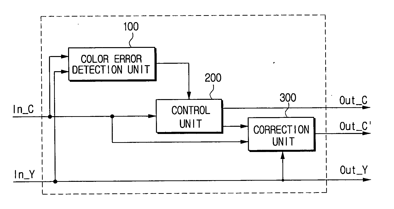
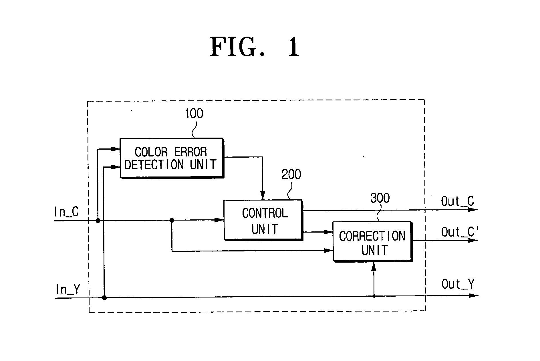
[0030]FIG. 1 is a block diagram of an apparatus for correcting a color error according to one embodiment of the present invention.

[0031] Referring to FIG. 1, the apparatus for correcting a color error includes a color error detection unit 100, a control unit 200, and a correction unit 300.

[0032] The color error detection unit 100 detects whether there is a color error in an edge region based on a difference value between interlaced horizontal lines and a difference value between non-interlaced horizontal lines in a luminance signal and a chrominance signal, respectively, located in an edge region of an input video.

[0033] In case a color error exists in the edge region, for chrominance signals the average of difference values between interlaced horizontal lines is smaller than the average of difference values between non-interlaced horizontal lines, whereas for...


PUM


Abstract

An apparatus for correcting a color error, including: a color error detection unit for detecting the presence or absence of a color error in an edge region of an input video, based on a relation between difference values between interlaced horizontal lines and difference values between non-interlaced horizontal lines of chrominance and luminance signals, respectively; a correction unit for correcting the color error by performing chroma filtering on the chrominance signals of the input video, if the color edge is present in the edge region; and a control unit for controlling the chrominance signals to be outputted after being corrected if the color error is present in the edge region, and for controlling the input chrominance signals to be outputted as they are if the color error is not present in the edge region.

Description

CROSS-REFERENCE TO RELATED APPLICATIONS [0001] This application claims benefit under 35 U.S.C. § 119 from Korean Patent Application No. 2005-75445, filed on Aug. 17, 2005, the entire content of which is incorporated herein by reference. BACKGROUND OF THE INVENTION [0002] 1. Field of the Invention [0003] The present invention relates in general to an apparatus for correcting a color error and a method thereof, and more particularly, to an apparatus and method for correcting a color error by detecting a color error and adaptively filtering chrominance signals. [0004] 2. Description of the Related Art [0005] Because a chrominance signal has a relatively lower resolution than a luminance signal, chrominance may be sampled at a lower rate of luminance. MPEG defines different chrominance formats, such as, 4:2:0, 4:2:2 and 4:4:4, according to the sampling method of a chrominance signal. For instance, a horizontal scan line on a TV screen is expressed as a ratio of three components: luminan...

Claims


Application Information

Patent Timeline
Patent Type & Authority Applications(United States)
IPC IPC(8): H04N5/00
CPCH04N9/646H04N9/77H04N9/64
Inventor HONG, KI-HYUN
Owner SAMSUNG ELECTRONICS CO LTD
Learn More