Medical lighting apparatus

a technology for lighting apparatus and medical devices, applied in lighting and heating apparatus, semiconductor devices for light sources, lighting support devices, etc., can solve the problems of low-temperature burns, significant amount, affected areas of patients, etc., and achieve uniform light distribution, enhance color rendering properties, and improve color rendering properties.

a technology for lighting apparatus and medical devices, applied in lighting and heating apparatus, semiconductor devices for light sources, lighting support devices, etc., can solve the problems of low-temperature burns, significant amount, affected areas of patients, etc., and achieve uniform light distribution, enhance color rendering properties, and improve color rendering properties.

US20070041167A1Inactive Publication Date: 2007-02-22DAI ICHI SHOMEI

Image

  • Medical lighting apparatus
  • Medical lighting apparatus
  • Medical lighting apparatus

Examples


Embodiment Construction

[0027] The present invention will hereunder be described in conjunction with a preferred embodiment of the invention which is shown in the drawings. In the drawings like reference numerals are used throughout the various views to designate like parts.

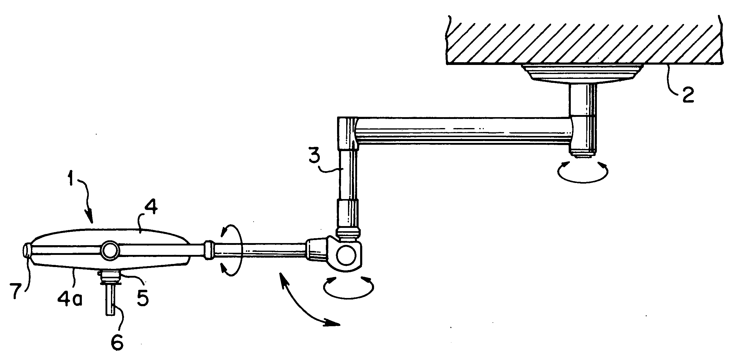
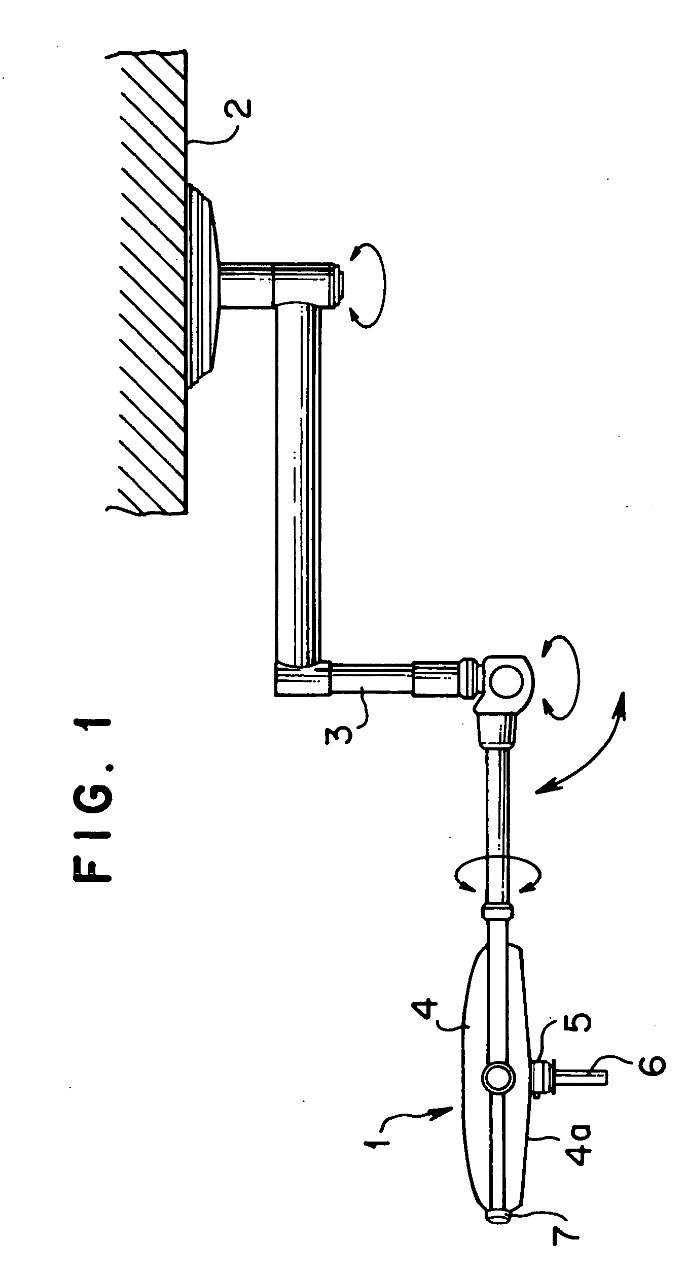
[0028]FIGS. 1 through 7 show an embodiment of the present invention. As shown in FIG. 1, a medical lighting apparatus 1 of the present embodiment is mounted on the ceiling 2, etc. of an operating theater, etc. through an arm 3 so that its position and posture are freely changeable.

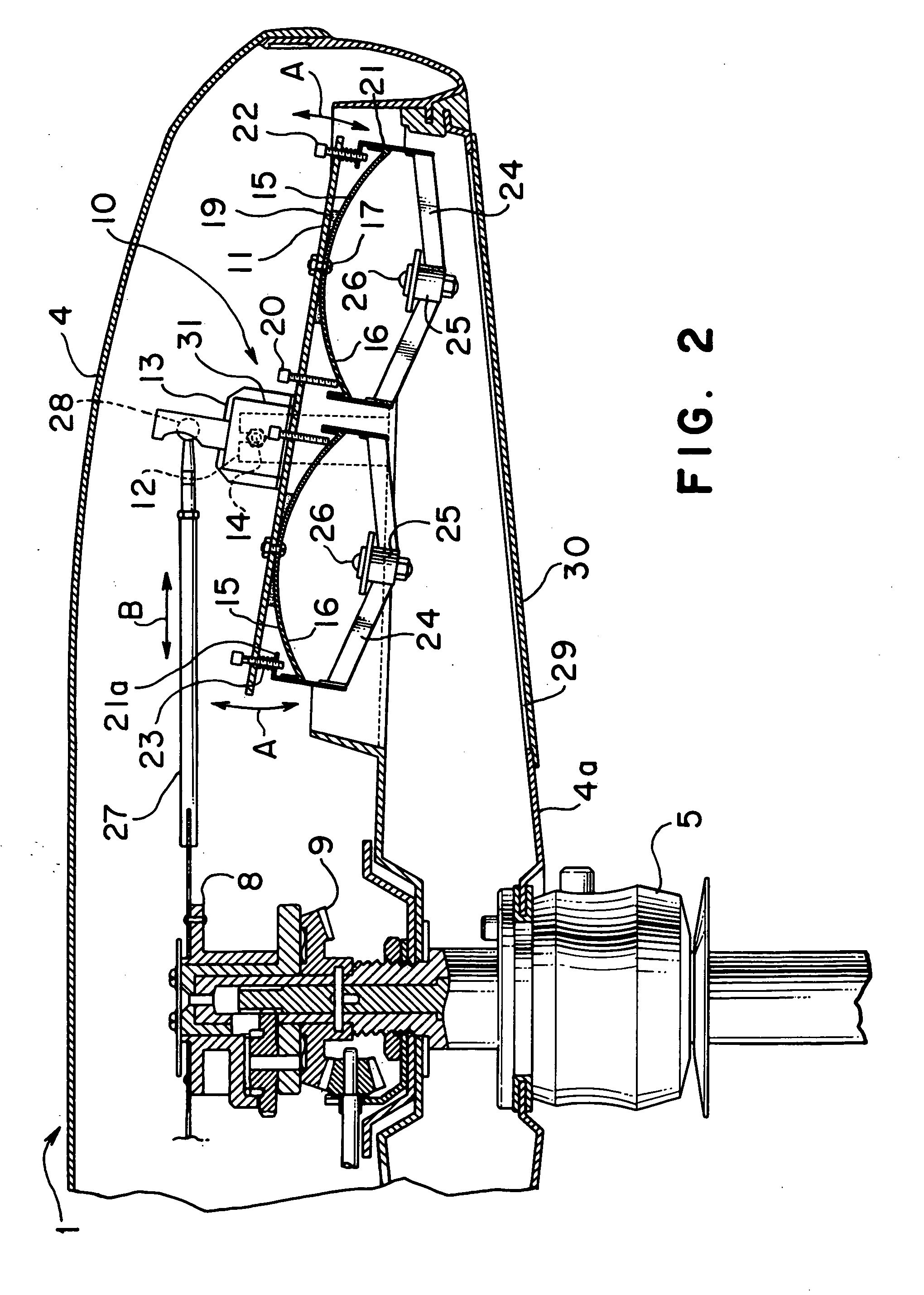
[0029] As shown FIG. 1 through 3, the medical lighting apparatus 1 has a generally saucer-shaped light main body 4, on the center of which lower part a coupler 5 is mounted protruding outside and downward. A center focus handle 6 is detachably mounted to the coupler 5. As shown in FIGS. 1 and 3, a focus control knob 7 is rotatably mounted on the outer periphery of the main body 4. The center focus handle 6 and the focus control knob 7 constitute focusing mem...


PUM


Abstract

A medical lighting apparatus includes single or plural LED units. Each of the LED units comprises a plurality of concave reflecting surfaces and an LED element disposed in front of each of the reflecting surface so as to radiate light toward each of the reflecting surfaces. Each of the LED units is arranged so that the lights radiated from its LED elements are reflected by the reflecting surfaces, emerge outside and are superimposed on one another on an area to be illuminated, respectively, while illuminating the area. The LED elements of each of the LED units comprise a combination of different emitting colors so as to enhance the color rendering properties.

Description

BACKGROUND OF THE INVENTION [0001] 1. Field of the Invention [0002] This invention relates to a medical lighting apparatus for illuminating an area such as an operative area of a patient in the medical field. [0003] 2. Related Art [0004] This kind of conventional medical lighting apparatus employs incandescent bulbs such as halogen lamps as the light sources (see, for example, Japanese Laid-Open Patent Publication No. 4-312457). [0005] The conventional medical lighting apparatus using incandescent bulbs presents the following problems, since the light sources generate a significant amount of heat. There is danger of the heat drying out an affected area of a patient or causing a low-temperature burn. The heat also causes discomfort to an operator with being radiated to his or her head, neck or shoulder. [0006] On the other hand, recently high-intensity LEDs (Light Emitting Diodes) have been developed and they generate much less heat than incandescent bulbs. Therefore, it can be expec...

Claims


Application Information

Patent Timeline
22 Feb 2007
Publication
US20070041167A1
IPC
A61G13/00
CPC
F21S2/005; F21V7/0008; F21V7/06; F21V14/02; F21V14/04; F21V17/02; F21Y2115/10; F21V21/30
Inventors
NACHI, AKIO