Quality of service monitoring architecture, related method, network and computer program product

Active Publication Date: 2007-02-22
TELECOM ITALIA SPA
View PDF10 Cites 76 Cited by
  • Summary
  • Abstract
  • Description
  • Claims
  • Application Information

AI Technical Summary

Benefits of technology

[0052] The system, which is scaleable and modular, excellently meets the requirements of security and reliability of the measured data, functional and perf...

Problems solved by technology

The complexity and heterogeneity of the mobile radio network environment (limited capacity of radio resources, mobility, integration with fixed networks, limited dimensions of the screen and keyboard of the terminal, etc.) and of the services offered therein (e.g. localisation, MMS, video streaming, multimedia) make it difficult to obtain an accurate and punctual measurement of the dynamically variable quality levels experienced during a communication.
These measurements indirectly increase the offered quality level, but are not capable of directly evaluating it in the quantitative and qualitative sense in relation to the quality perceived by the user; on monitoring, under actual traffic conditions, the performance of shared network and link resources at the transport level (normally carried out by the mobile radio operator with internal or external measures, taken by sampling or total with counter, but almost never inclusive of the terminal and hence not end-to-end and not at application level), with evident limits to the ability to correlate said measures to the communication quality actually perceived by the user, also deriving from the difficulty of activating co-ordinated measuring campaigns in the network on a call and/or service session basis; on measurement campaigns under artificial traffic conditions, conducted using terminals and/or specialised equipment (whose characteristics are not always equivalent to the commercial mobile radio terminals utilised by users), with obvious deficiencies from t...

Method used


Image

  • Quality of service monitoring architecture, related method, network and computer program product
  • Quality of service monitoring architecture, related method, network and computer program product
  • Quality of service monitoring architecture, related method, network and computer program product

Examples


Embodiment Construction

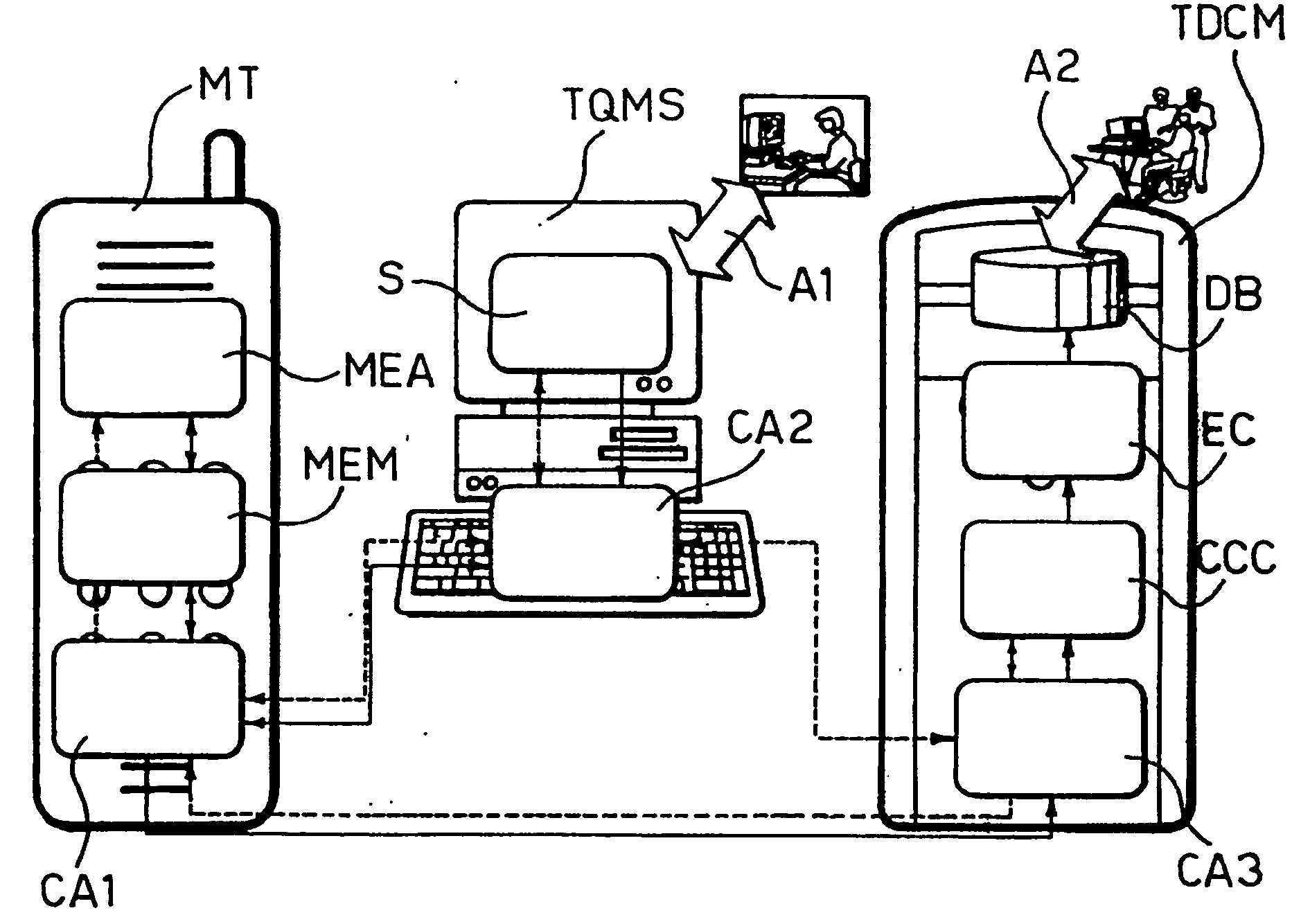
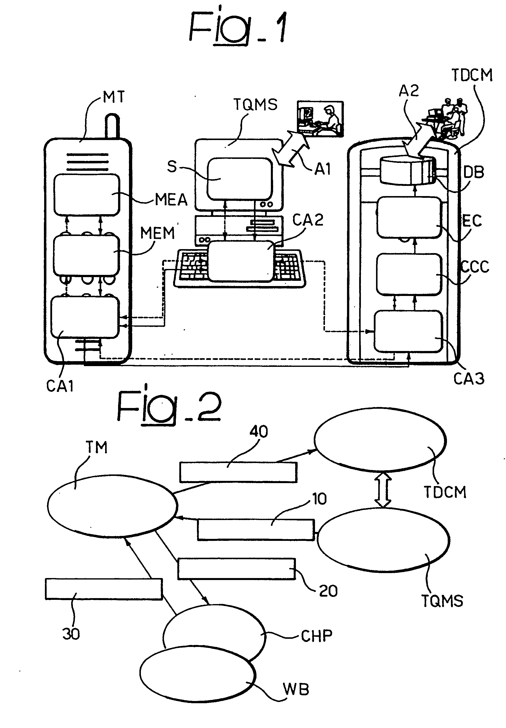
[0058]FIG. 1 shows the general architecture of the system described herein, highlighting the function modules which compose it and the location of the communication and measurement agents. Also indicated are the external interactions both from / to a user of the system and to external systems for the collection, analysis, reporting of the results.

[0059] Briefly, referring to the (preferred, but not imperative) application to a mobile communication network—according to any standard—at the mobile terminal MT level the following are provided: [0060] a measuring agent MEA (Measurement Executor Agent), [0061] a Measurement Elaboration Module (MEM), and [0062] a Communication Agent CA1.

[0063] At the level of the management and configuration system, overseeing the measurements (indicated herein as TQMS, with reference to the typical role of the Terminal Quality Measurement Scheduler) are instead present: [0064] a measurement campaign scheduler S, [0065] a communication agent CA2, and [0066...


PUM


Abstract

An architecture for monitoring quality of service in a telecommunication network having a set of terminals provides for the terminals of the set of terminals to house measuring agents able to be configured to interface with processes selected among processes for managing the application sessions of the network and processes for measuring the operating conditions of the network itself. Also provided is a management and configuration sub-system having a module for scheduling quality of service measurement campaigns capable of involving respective sub-sets of terminals according to a set of characteristics identifying the measurement campaign. The scheduling module is capable of configuring, for the purposes of the execution of the measurement campaigns, the measuring agents housed by the terminals included in the related subsets according to the set of identifying characteristics. An additional sub-system for managing the collection of the measurement data has a database for storing the measurement data and a processing centre for processing the data.

Description

FIELD OF THE INVENTION [0001] The present invention relates to techniques for monitoring Quality of Services (QoS) in telecommunication networks. The invention was developed with particular attention to its possible application to mobile communication network. However, reference to this particular field of possible application must not be construed as limiting the scope of the invention. DESCRIPTION OF THE PRIOR ART [0002] With the emergence and development of mobile networks, from GSM to GPRS and, more recently, to UMTS, the variety and the number of voice, data, multimedia services available or emerging in this field is growing both in terms of functional characteristics, and in regard to performance requirements, to meet needs expressed by the user or deriving from an ever more competitive market. [0003] For a provider of mobile services, being able to obtain a qualitative benchmark on its services is increasingly becoming a factor for success and market penetration, as well as f...

Claims


Application Information

Patent Timeline
IPC IPC(8): H04J1/16H04L12/28H04W24/00H04W28/24H04W72/12
CPCH04W24/00H04W28/24H04W72/121
Inventor BOSTICA, PAOLOBIZZARRI, SIMONEVITALE, MICHELE
Owner TELECOM ITALIA SPA
Why Eureka
Try Eureka