Machine tool

a technology of machine tools and struts, which is applied in the direction of turning apparatuses, mechanical control devices, large fixed members, etc., can solve the problems of complex measuring systems and precision requirements for positioning of second slide elements, and achieve the effect of keeping the thermal displacement in the drive strut region low

Inactive Publication Date: 2007-03-01
INDEX WERKE GMBH & CO KG HAHN & TESSKY
View PDF12 Cites 17 Cited by
  • Summary
  • Abstract
  • Description
  • Claims
  • Application Information

AI Technical Summary

Benefits of technology

[0047] The advantage of this solution can be seen in that the drive struts consequently extend from a region of the machine tool which undergoes minor thermal displacements with respect to the spindle axis, and consequently also the position of the movable slide elements that is predetermined by the drive device undergoes only minor thermal displacements.
[0048] Furthermore, it is advantageous in the case of this solution that, on account of their invariance of length, no heat directly enters the drive struts as a result of a length adjustment of the same, so that the thermal displacement in the region of the drive struts can also be kept low.
[0049] In the case of this solution, it is particularly advantageous if the guideways for the guiding slides are disposed near a reference plane which runs through the spindle axis and perpendicularly in relation to the X direction of the machine tool.
[0050] This solution has the great advantage that the base for the drive struts of the drive device consequently already lies near the spindle axis, and consequently substantially only thermal displacements in the region of the drive struts have any effect on the position of the movable slide element, while all other thermal displacements, in particular in the machine bed body, have substantially no effect on the position of the movable slide element in relation to the spindle axis.
[0051] It is particularly advantageous if the guideways for all the guiding slides are disposed on the side of the points of application facing the spindle axis, so that all the drive struts have an effect on the positioning accuracy in the same direction in the event of a thermally induced change in their length.

Problems solved by technology

In the case of a machine tool of this type, it has been found that the required precision in the positioning of the second slide element requires complex measuring systems.

Method used


Image

  • Machine tool
  • Machine tool
  • Machine tool

Examples


Embodiment Construction

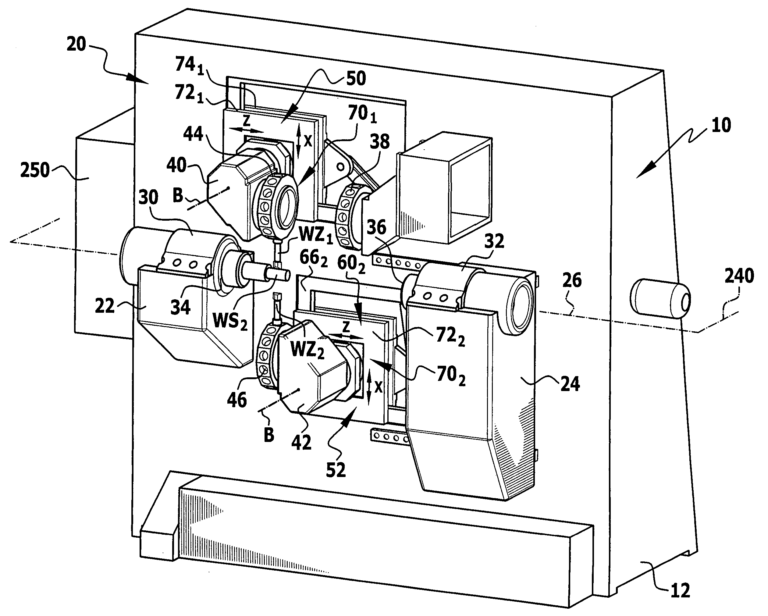
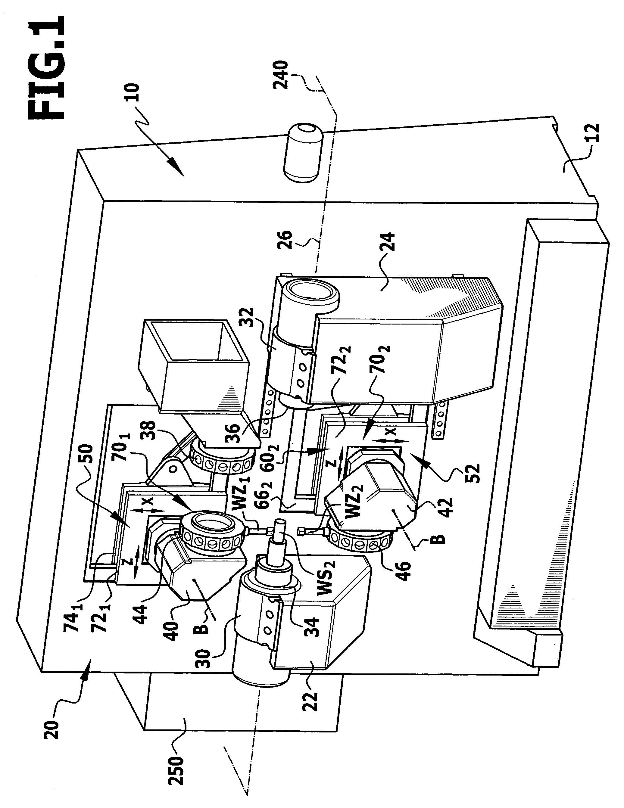
[0058] An exemplary embodiment of a machine tool according to the invention, represented in FIG. 1, comprises a machine frame, which is designated as a whole by 10, can be placed with a foot 12 on a base area and comprises a machine bed body, which is designated as a whole by 20 and is preferably formed in a way similar to a plate.

[0059] On this machine bed body 20 there are, for example, two headstocks 22, 24, in which workpiece spindles 30, 32 are disposed coaxially in relation to a spindle axis 26, lie opposite each other and are provided with workpiece receiving means 34, 36 for workpieces WS, which represent first receiving means and are disposed facing one another.

[0060] In this case, the machine tool represents a lathe.

[0061] However, instead of workpiece spindles 30, 32, it would also be conceivable to provide tool spindles with tool receiving means.

[0062] In the case of this exemplary embodiment of the machine tool according to the invention, the headstock 22 is dispose...


PUM

PropertyMeasurementUnit
lengthaaaaaaaaaa
movementaaaaaaaaaa
torsional stiffnessaaaaaaaaaa

Abstract

In order to improve a machine tool for machining a workpiece by a relative movement between the workpiece and a tool, comprising a first receiving means for the workpiece or the tool, a compound slide system with a second receiving means for the tool or the workpiece and comprising a drive device for moving the second receiving means in relation to the first receiving means, which drive device acts at at least two spaced-apart points of application by at least three drive struts extending parallel to at least two different directions and each with a pivot joint, and with which drive device the at least two points of application can be positioned by means of the at least three drive struts, in such a way that exact positioning of the second slide element can be achieved by structural measures, it is proposed that four drive struts of invariant length, each with a pivot joint, act on the slide element, each of which struts is pivotally connected to a guiding slide, which is guided in a linearly movable manner transversely in relation to the longitudinal direction of the respective drive struts, and a maximum of two of which drive struts run parallel to one another.

Description

CROSS-REFERENCE TO RELATED PATENT APPLICATIONS [0001] This patent application claims the benefit of German Application No. 10 2005 041 496.6, filed Sep. 1, 2005, the teachings and disclosure of which are hereby incorporated in its entirety by reference thereto. BACKGROUND OF THE INVENTION [0002] The invention relates to a machine tool for machining a workpiece by a relative movement between the workpiece and a tool, comprising a machine frame, a carrier disposed on the machine frame and having a first receiving means for the workpiece or tool, a compound slide system disposed on the machine frame and having a slide element which carries a second receiving means for the tool or the workpiece and can be moved by the compound slide system in relation to the first receiving means in a fixed movement zone of a compound slide movement area in the direction of two compound slide movement axes running transversely in relation to one another and comprising a drive device for moving the slide...

Claims


Application Information

Patent Timeline
Patent Type & Authority Applications(United States)
IPC IPC(8): B23P23/00
CPCB23Q1/5462Y10S414/13Y10T409/309576Y10T29/5114Y10T82/2506Y10T29/5153Y10T74/20305Y10T74/20354Y10T74/2036Y10T409/307672Y10T74/20341
Inventor GROSSMANN, WALTER
Owner INDEX WERKE GMBH & CO KG HAHN & TESSKY
Why Eureka
Try Eureka