Hair clipper

a clipper and hair technology, applied in the field of hair clippers, can solve the problems of unable to secure the strength of the comb-tooth, and unable to achieve the effect of ensuring the strength, and reducing the chance of cutting hair

Active Publication Date: 2007-03-01
PANASONIC CORP
View PDF10 Cites 21 Cited by
  • Summary
  • Abstract
  • Description
  • Claims
  • Application Information

AI Technical Summary

Benefits of technology

[0011] According to the hair clipper having the above structure, when hair is to be cut, hair which hits on the guide projection 21 of the fixed blade 2 slips on both tapered surfaces of the inclination angle 1 of the guide projection 21, and the hair is efficiently introduced between the adjacent comb-teeth 2a without falling. Further, the comb-teeth 2a of inclination angle α can keep sufficient width from its root to its tip and thus, the strength can be secured although the projecting length for adjusting the cutting height is long. In addition, since the inclination angle α of the comb-teeth 2a itself is small, the root width of the comb-teeth 2a does not become excessively wide, and the number of teeth is secured.
[0012] It is preferable that the tip width of the guide projection 21 is equal to or smaller than a width of hair. As a result, the efficiency in introducing hair is further enhanced.

Problems solved by technology

For the fixed blade 50 of a hair clipper whose cutting height can be adjusted, however, since it is necessary to largely set the projecting length of the comb-tooth 51 if the tip width of the comb-tooth 51 is reduced as small as about 0.1 millimeter, the entire comb-tooth 51 becomes thin, and there is a problem that the strength thereof cannot be secured.
As a result, there is a problem that chances for cutting hair are reduced or hairs easily escape from the blade groove 52.

Method used


Image

  • Hair clipper
  • Hair clipper
  • Hair clipper

Examples


Embodiment Construction

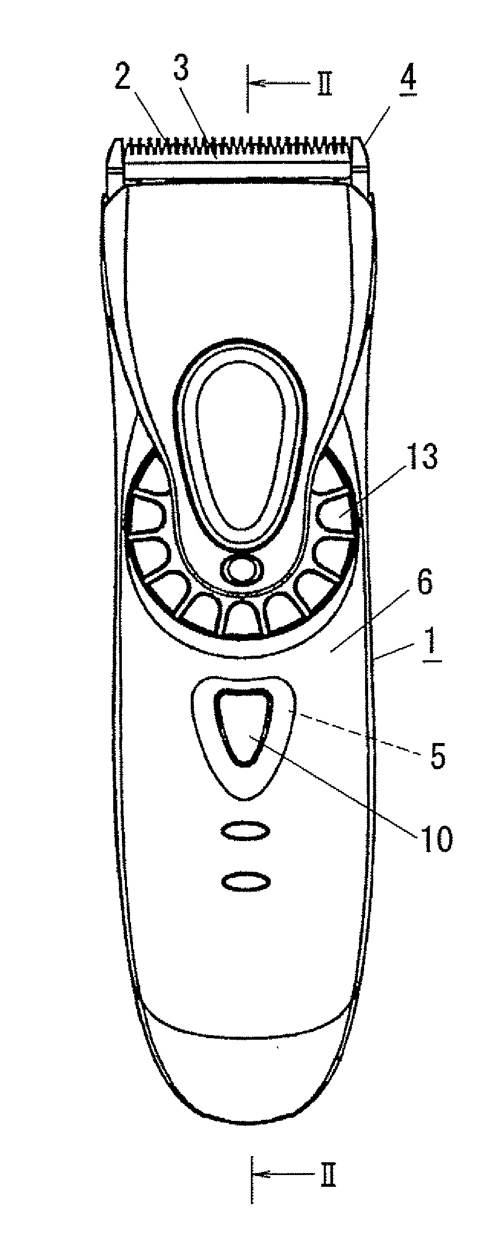
[0022] Embodiments of the present invention will be explained below with reference to the drawings. One example of a hair clipper according to an embodiment of the present invention has a thin and long main body 1 which also functions as a grip as shown in FIGS. 4A and 4B. A blade block 4 having a fixed blade 2 and a movable blade 3 is mounted on the top the main body 1 in its longitudinal direction (upper end in FIGS. 4A and 4B) The movable blade 3 of the blade block 4 is reciprocated while sliding in the lateral direction (in FIG. 4B) with respect to the fixed blade 2 by a motor disposed in the main body 1 as a driving source, so that hair introduced into the blade grooves 2b on the tip of the fixed blade 2 is hold between the movable blade 3 and cut.

[0023] As shown in FIG. 5, the main body 1 has a main body housing 6 forming a substantially S-shaped outer envelope as viewed from side. A user can grasp the main body housing 6 with his or her one hand. Accommodated in the man body...


PUM


Abstract

The hair clipper comprises comb-like fixed blade and movable blade each having a plurality of comb-teeth each provided at its both sides with blades, in which the movable blade is reciprocated with respect to the fixed blade in an arrangement direction of the comb-teeth to cut hair, the fixed blade or the movable blade is slid in a projecting direction of the comb-teeth to adjust cutting height, wherein a tip of each comb-tooth of the fixed blade is provided with a guide projection for introducing hair, the guide projection is tapered with an inclination angle which is larger than an inclination angle of the comb-tooth with respect to projecting direction of blades on both sides of the comb-tooth.

Description

CROSS REFERENCE TO RELATED APPLICATION [0001] This application is based upon and claims the benefit of priority from prior Japanese Patent-Application P 2005-246797, filed on Aug. 26, 2005; the entire contents of which are incorporated by reference herein.BACKGROUND OF THE INVENTION [0002] 1. Field of the Invention [0003] The present invention relates to a hair clipper for cutting hair by reciprocating a movable blade with respect to a fixed blade. [0004] 2. Description of the Related Art [0005] Conventionally, there is a known hair clipper comprising comb-like fixed blade and movable blade having a plurality of comb-teeth provided at their both sides with blades. This hair clipper is used for cutting hair by reciprocating the movable blade with respect to the fixed blade in an arrangement direction of the comb-teeth. The cutting height can be adjusted by sliding the movable blade with respect to the fixed blade in a projecting direction of the comb-teeth (see Japanese Patent Applic...

Claims


Application Information

Patent Timeline
Patent Type & Authority Applications(United States)
IPC IPC(8): B26B19/00
CPCB26B19/3846B26B19/205B26B19/06B26B19/04
Inventor FUKUTANI, MAKOTOIKUTA, TOSHIOINABA, JIRO
Owner PANASONIC CORP
Why Eureka
Try Eureka