Modular building construction employing concrete mold assembly

a technology of concrete molds and modular components, applied in special buildings, parkings, walls, etc., can solve the problem of more difficult construction of modular components under the same limitations

Inactive Publication Date: 2007-03-01
LEBLANG DENNIS
View PDF18 Cites 36 Cited by
  • Summary
  • Abstract
  • Description
  • Claims
  • Application Information

AI Technical Summary

Problems solved by technology

However, conventionally is brought to the construction site unfinished on the interior with an exterior sheathing, such as plywood or insulation, forming a structural system of wood joists or metal light gauge metal channels.
The panelized technique has similar size restrictions, but constructing a modular component under the same limitations is more difficult.

Method used


Image

  • Modular building construction employing concrete mold assembly
  • Modular building construction employing concrete mold assembly
  • Modular building construction employing concrete mold assembly

Examples


Embodiment Construction

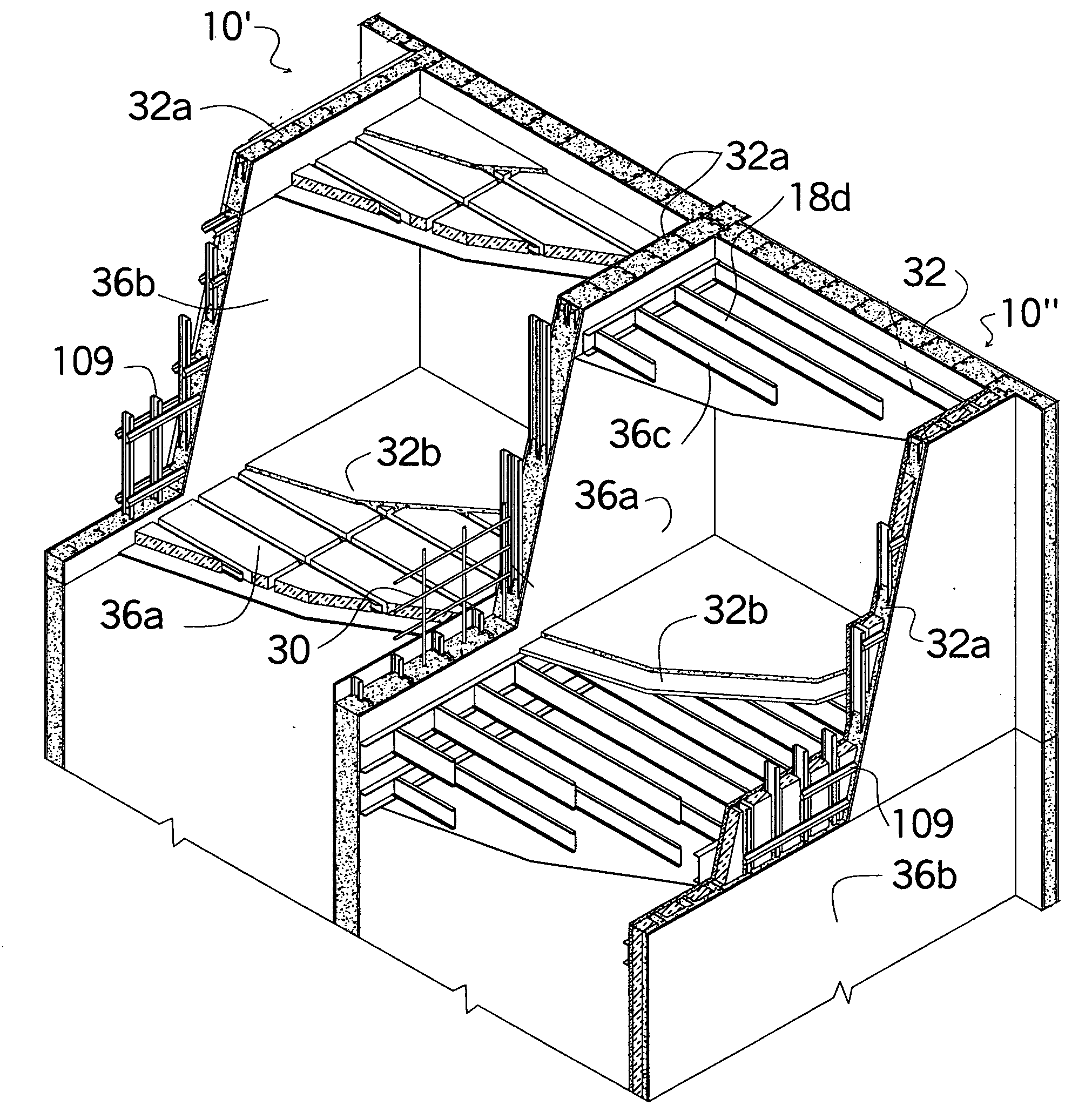
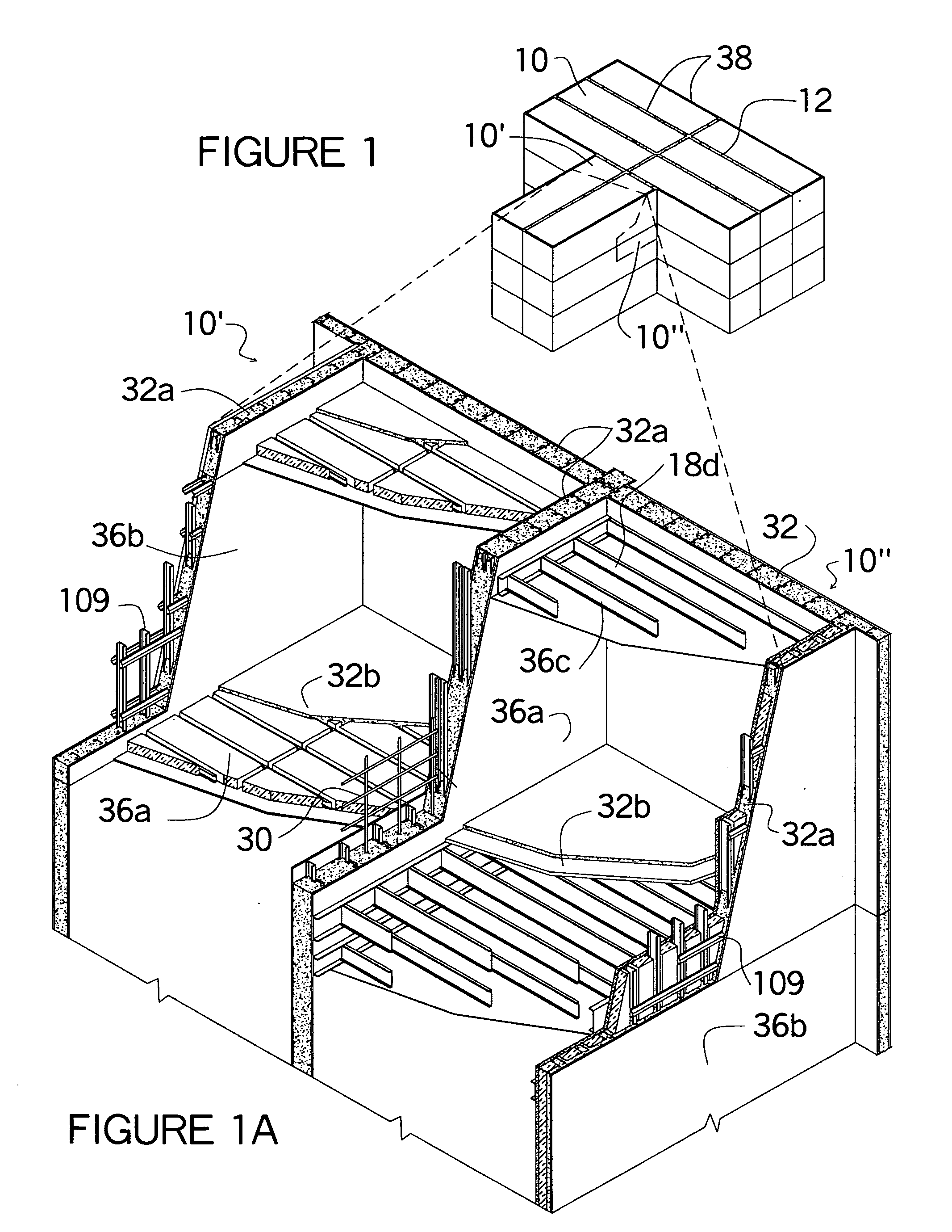
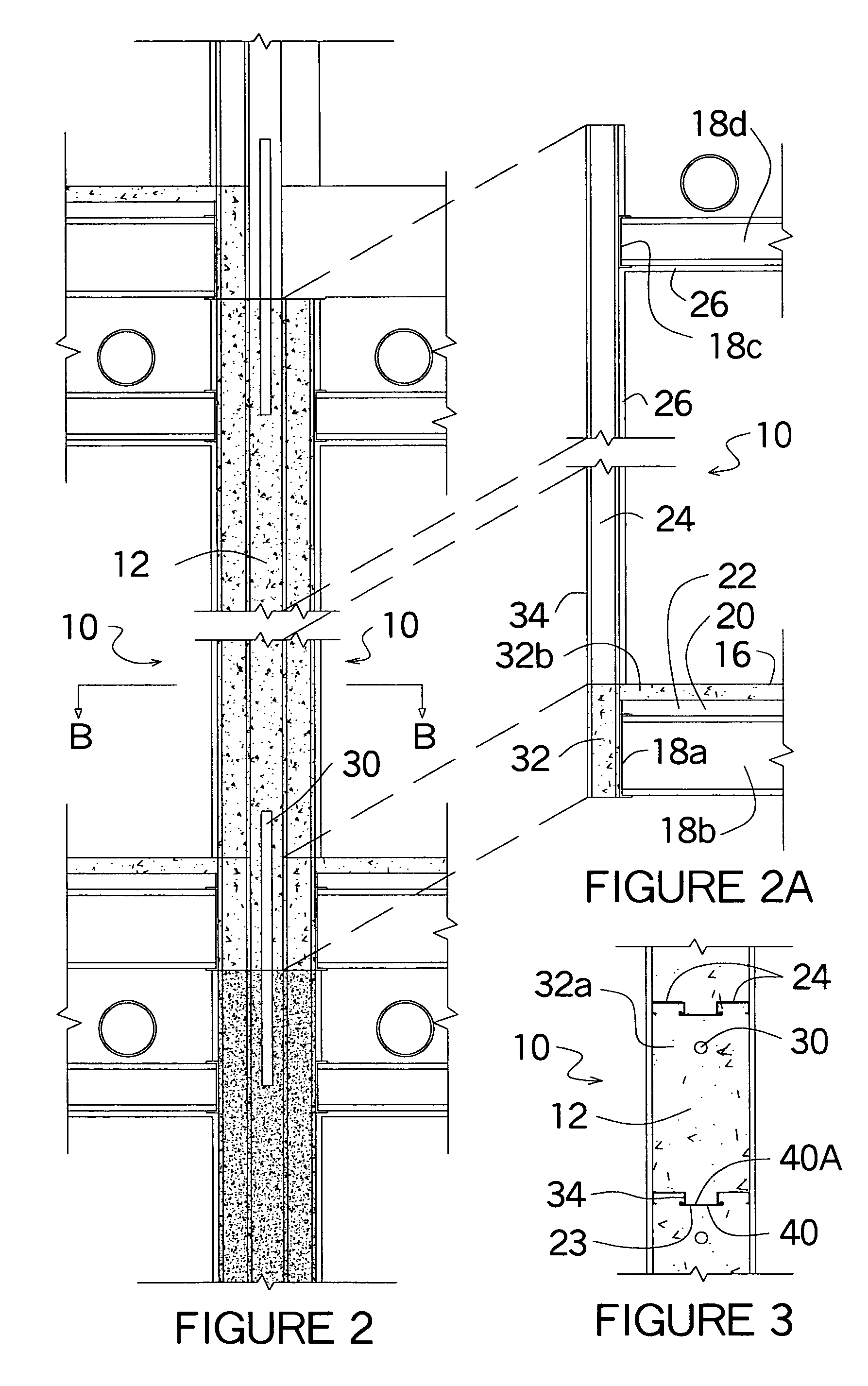
[0102] The self-contained mold according to the invention is formed by installation of two or more wall panels or the wall of several modular components placed adjacent to one another, however spaced apart to allow for concrete to form between the panels or modules. The wall sections can be composed of metal construction or wood construction with the interior finish, preferably, to be the interior finish of the structure. The structural wood studs or steel studs, as well as the interior finish material, as a part of the structure and are not removed. Both galvanized steel, or wood fire rating capabilities, however, are nothing like the fire rating of concrete. The encasement of the steel studs or wood studs into concrete, increasing the structural capacity, as well as increasing the fire rating of the wall component. The prevention of air around the wall studs decreases the cause for a fire to start. Increasing the size of wood studs increases the strength and decreases the gauge si...


PUM


Abstract

A modular building construction where each module consists of self-contained molds to allow concrete to form within the walls of each module as well as between the modules when two or more modules are placed together. The structural load capacities of the modules are transmitted directly into the concrete within the wall without bearing directly on the module below. The forming structure for the modules can be fabricated either using wood or metal construction. The exterior and interior wall finishes are the resulting structure of the molds. Since the molds are self-contained the walls can consist of, either drywall, rigid insulation, thin brick or siding just to name a few. The interior forming structure can extend into the concrete footing or above or to adjacent modules to structurally secure the modules together. The modules can be built with a flooring structure as well as ceiling. The interior walls as well as the floor and ceiling also function as wall supporting braces. The exterior walls have many different forming molds to accommodate many different construction situations. Some forming structures are formed with a thermal break between the exterior and interior forming structure. The thermal break allows the wall to also be used as a heating or cooling distribution system. Different types of connectors are described allowing for the connectors to be hidden. Several methods are shown how the electrical distribution can be provided within a concrete wall by using the forming structure within the mold. A ribbed concrete mold can be formed for a poured-in-place wall as well as for a floor and roof system. Temporary floor bracing can be used when pouring the flooring system, or only just the concrete beams can be poured and the floor can be poured later. The flooring system can be used as concrete wall or as a roof structure.

Description

FIELD OF THE INVENTION [0001] The invention is directed to a modular building construction involving the assembly of panelized and modular building units manufactured off site and installed on site, said units employing on site molded concrete juncture means, said units consisting of walled one, or a combination of walls, floor and ceiling section modules assembled and unified on site. DESCRIPTION OF THE PRIOR ART [0002] The building has been constructed by the assembly of off site manufactured floor, wall and ceiling components brought to a building site and individually installed and unified at a construction site as a unified structure. The finished materials are exposed to the inside of the structure, for example, typically drywall is installed on the walls and ceiling. The floor of the unit is usually finished in carpet, ceramic or vinyl tile with the under layer of the floor being either concrete or wood sub floor finished. However, conventionally is brought to the constructio...

Claims


Application Information

Patent Timeline
Patent Type & Authority Applications(United States)
IPC IPC(8): E04H1/00E04H3/00
CPCE04B1/161E04B2/8635E04B2/8647E04B2/8652
Inventor LEBLANG, DENNIS
Owner LEBLANG DENNIS
Why Eureka
Try Eureka