Rebar spacer and method

a technology of rebar spacers and rebars, applied in the direction of building reinforcements, constructions, building components, etc., can solve the problems of premature degradation, inability to achieve the desired structural characteristics of the structure, and considerable effort expended in the design of reinforced concrete structures

Inactive Publication Date: 2007-03-01
FUNK MATT
View PDF23 Cites 15 Cited by
  • Summary
  • Abstract
  • Description
  • Claims
  • Application Information

AI Technical Summary

Benefits of technology

[0008] It has been recognized that it would be desirable to have an apparatus and method for placing rebar within concrete forms that encourages proper placement of the rebar and helps secure it better.
[0009] It has also be recognized that it would be desirable to have an apparatus and method for encouraging proper rebar placement that is inexpensive and simple to use.

Problems solved by technology

Considerable effort is expended in the design of reinforced concrete structures to determine and specify the optimum amount and location of rebar.
Consequently, one persistent challenge in the subsequent construction of the structure is the proper placement of metal reinforcement within the concrete forms and keeping the reinforcement properly aligned (so as to provide adequate and consistent reinforcement) and with proper clearance from outer surfaces of the finished structure (so as to protect the reinforcement from exposure to the environment).
If the steel is not placed according to the design, the resulting structure may not have the desired structural characteristics, and / or may be subject to premature degradation from environmental factors and age.
Unfortunately, forces created by the flow of wet concrete during placement can shift and move rebar from its intended position even when rebar fixing device are used properly, and this can easily go undetected by workers, even if they are paying close attention.
Furthermore, many devices for supporting and securing rebar are inadequate for their purpose, either because of design aspects or difficulty of use.
Unfortunately, in the construction industry, economic pressures constantly work against the effort to apply proper skill and attention to a given job.
Placing additional chairs and ties within a form in order to better secure the rebar in the proper place takes time and money.
Since the position of rebar within a concrete structure is generally not visible after the concrete is placed, shoddy work can easily go undetected during construction, and will generally not be noticed soon afterward except in extreme cases.
Such flaws are frequently only discoverable many years after construction, when warranties have expired and there is little chance of holding the builder accountable.
Furthermore, low wage, low skill laborers (as are frequently employed in the construction industry) may not possess the skill, knowledge or care needed to properly use devices that do exist to help with rebar placement, especially where such devices are cumbersome or difficult to use.

Method used


Image

  • Rebar spacer and method
  • Rebar spacer and method
  • Rebar spacer and method

Examples


Embodiment Construction

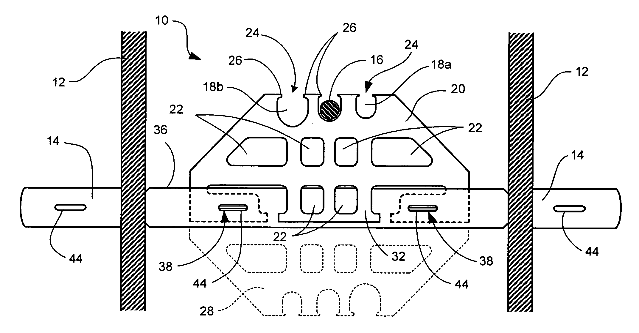
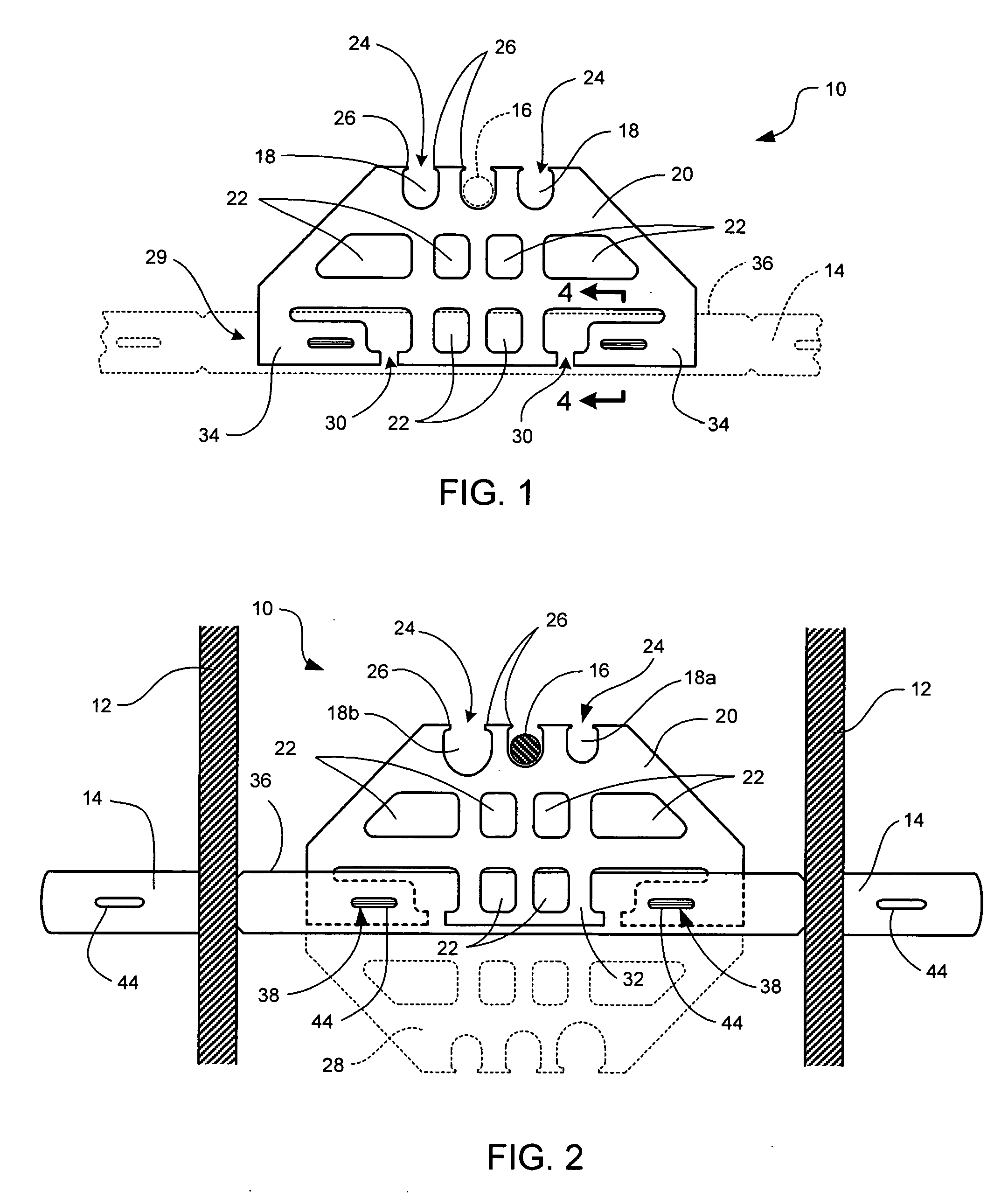
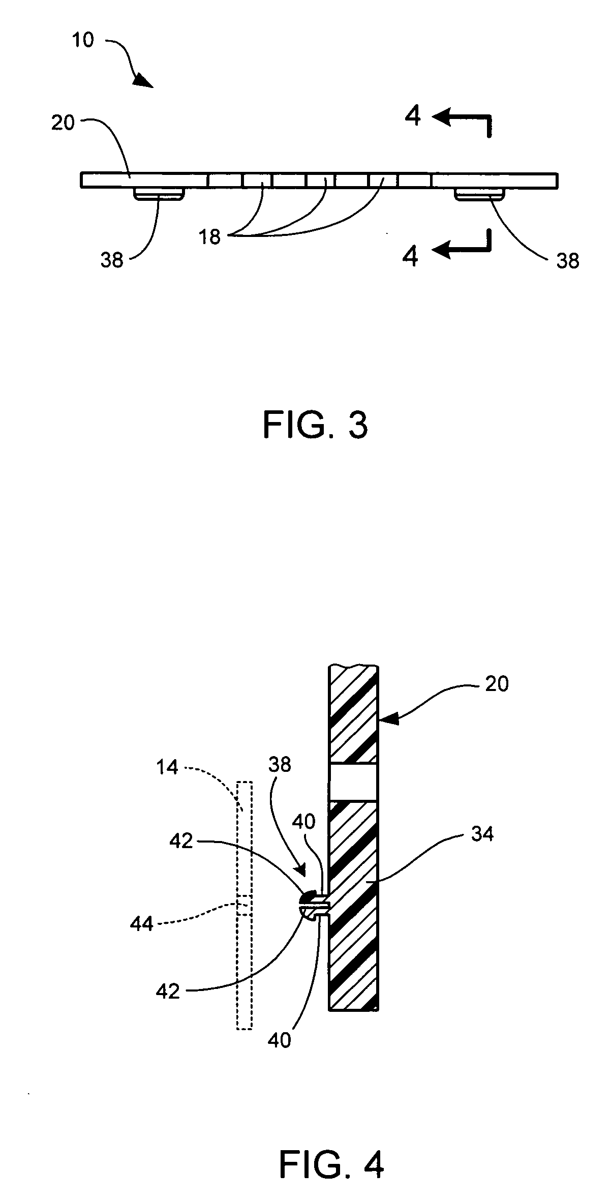
[0022] A front view of one embodiment of a rebar spacer 10 in accordance with the present invention is provided in FIG. 1, and a top view of the same is shown in FIG. 3. Shown in FIG. 2 is a cross-sectional view of opposing concrete forms 12 with a flat bar-type form tie 14 extending therebetween, and a rebar spacer disposed upon it. One piece of rebar 16 is shown in cross-section, disposed in one of the top slots 18 of the rebar spacer.

[0023] The rebar spacer 10 generally comprises a flat body 20 of non-metal material with a variety of openings formed in it. In the embodiment of FIG. 1, the top of the body includes several rebar apertures 18 that are open rounded slots designed to receive and support rebar 16 (shown in hidden lines in cross-section in FIG. 1) that is oriented substantially transverse to the body of the rebar spacer. Other openings 22 are also formed in the body. These openings perform several functions. They allow liquid concrete to flow through the body, so that ...


PUM

PropertyMeasurementUnit
diameteraaaaaaaaaa
diameteraaaaaaaaaa
diametersaaaaaaaaaa

Abstract

A device for supporting reinforcing bars within a form for a concrete wall having transverse form ties includes a non-metal body, configured to attach to a form tie in a fixed orientation. At least one aperture is disposed in the body, and is configured to receive an elongate reinforcing bar, so as to substantially fix the position of the reinforcing bar with respect to the form tie.

Description

BACKGROUND [0001] 1. Field of the Invention [0002] The present invention relates to devices for supporting and securing reinforcing bars for concrete construction. More specifically, the present invention relates to a device and method for supporting and securing rebar upon a form tie within a wall form. [0003] 2. Related Art [0004] Reinforced concrete is one of the most common and time-tested materials in modern building construction. The placement of ductile steel reinforcing bars (“rebar”) within a concrete mass gives the resulting structure the combined benefits of concrete's high compressive strength and steel's high tensile strength and ductility. Additionally, cast-in-place concrete can be formed into almost any shape, allowing the creation of beams, columns, arches, and other shapes in almost any desired form. [0005] It is well known that the strength and suitability of a reinforced concrete structure depends in part upon the quantity and location of the reinforcing steel. C...

Claims


Application Information

Patent Timeline
Patent Type & Authority Applications(United States)
IPC IPC(8): E04B1/38E04C5/00
CPCE04C5/168E04C5/20
Inventor FUNK, MATT
Owner FUNK MATT
Why Eureka
Try Eureka