Flow Meter

a flow meter and flow meter technology, applied in the field of flow meter, can solve problems such as complicated assembly operation, and achieve the effect of convenient operation

Active Publication Date: 2007-03-01
SMC CORP
View PDF11 Cites 3 Cited by
  • Summary
  • Abstract
  • Description
  • Claims
  • Application Information

AI Technical Summary

Benefits of technology

[0008] A general object of the present invention is to provide a flow meter in which a plurality of mesh memb

Problems solved by technology

Therefore, the assembly

Method used


Image

  • Flow Meter
  • Flow Meter
  • Flow Meter

Examples


Embodiment Construction

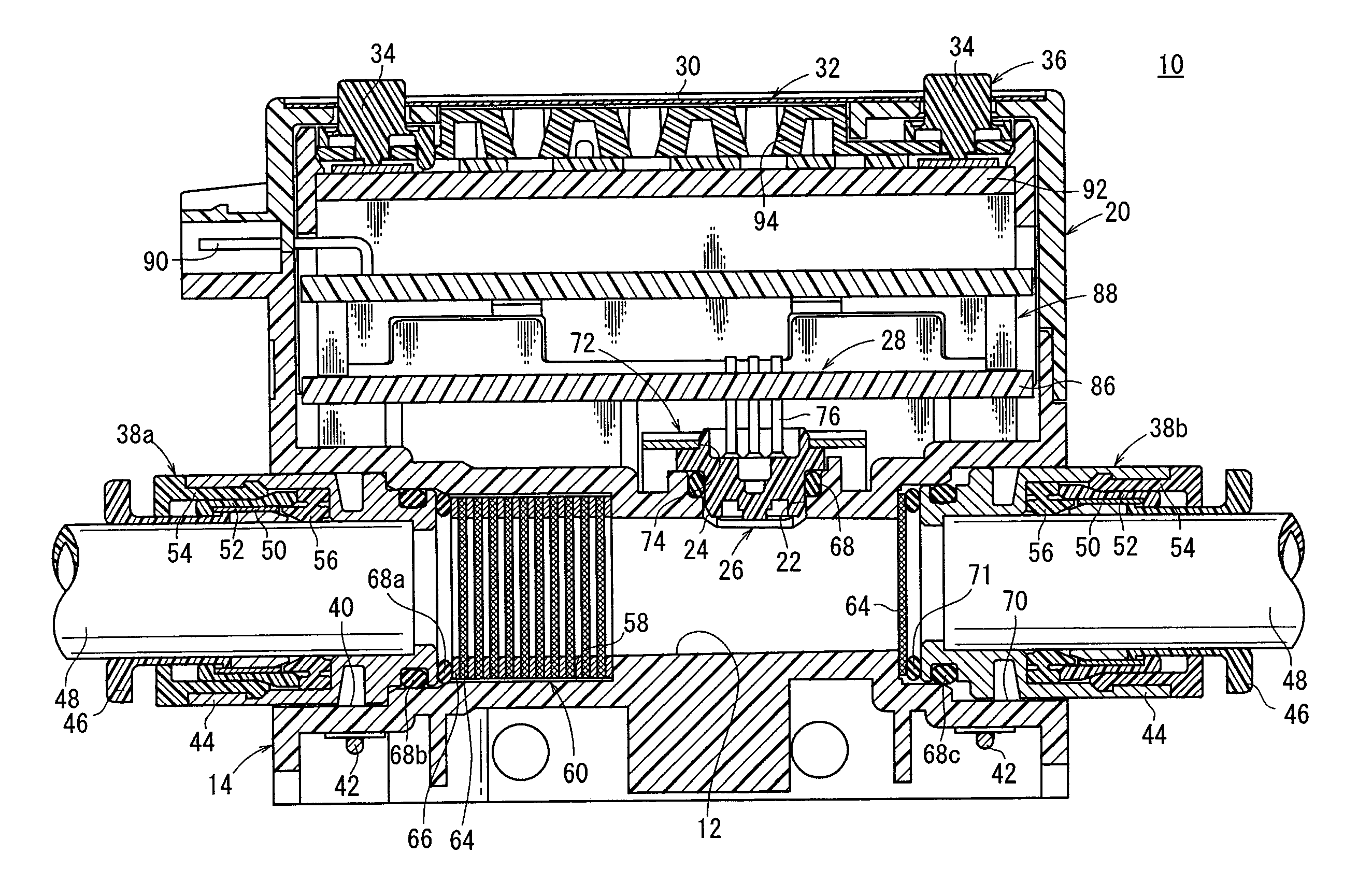
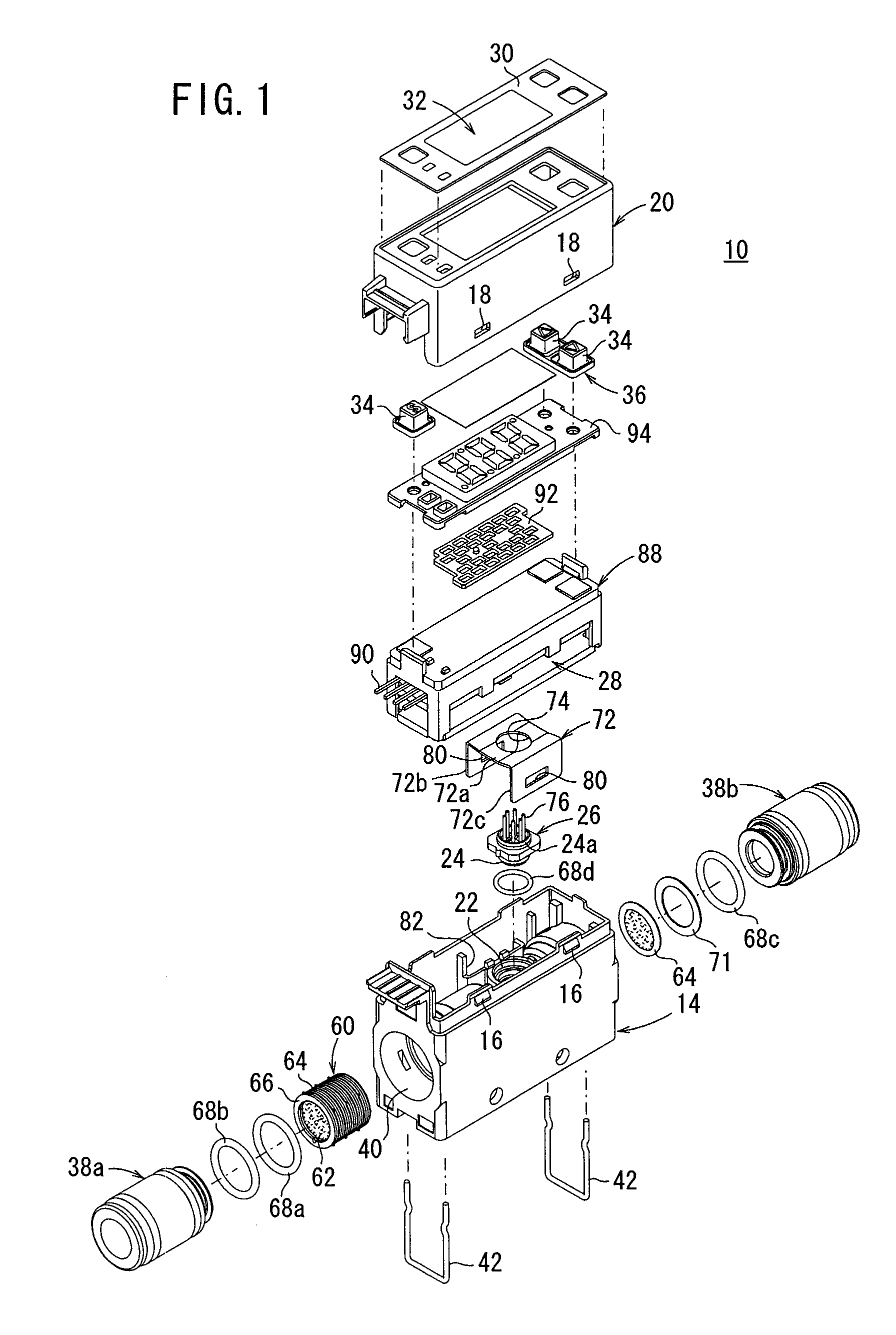
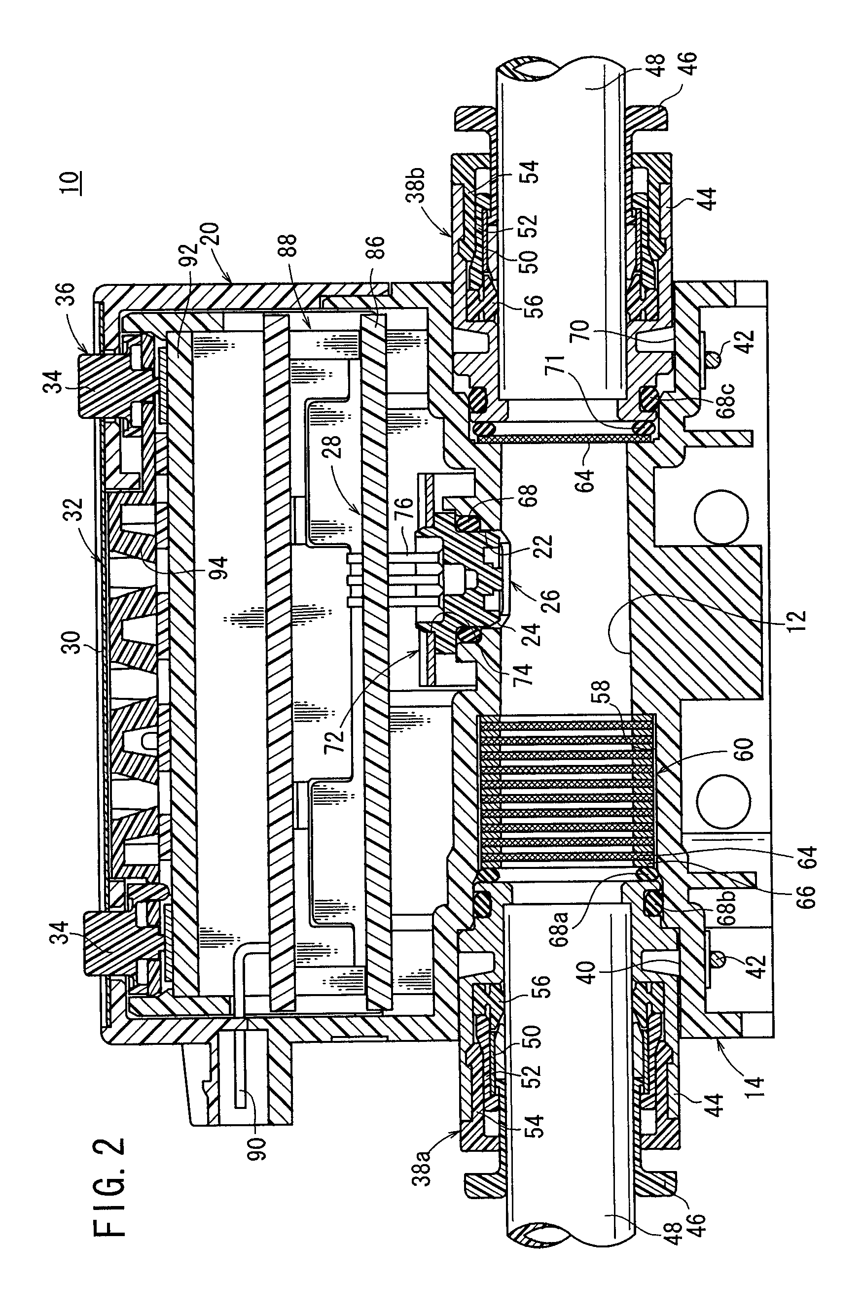
[0022] With reference to FIG. 1, reference numeral 10 indicates a flow meter according to an embodiment of the present invention.

[0023] The flow meter 10 comprises a body 14 made of resin, which is substantially rectangular parallelepiped-shaped, and includes a flow passage 12 (see FIG. 2) having a circular cross section that penetrates from one end surface to the other end surface in the axial direction through which a fluid to be measured flows. A rectangular parallelepiped-shaped housing 20 is provided, which is integrally assembled on an upper portion of the body 14 through engagement of rectangular holes 18 with pawls 16 that are formed on the body 14. In this arrangement, the body 14 and housing 20 function as a main body section.

[0024] The flow meter 10 further comprises a detecting section 26, which includes a flow velocity sensor 24 facing the flow passage 12 with a seating surface (seating section) of a circular opening 22 formed on the body 14, a control unit 28 provide...


PUM


Abstract

A rectifying module is arranged on an upstream side of a flow passage containing a flow velocity sensor. The rectifying module includes mesh members each having a plurality of circular small holes and ring-shaped spacers, wherein the mesh members and the spacers are alternately stacked in an axial direction and integrally joined to one another by means of thermal diffusion bonding. The mesh members have identical structures, in which the plurality of small holes are arranged concentrically at angles of separation of 60 degrees in the circumferential direction about the center of a reference small hole. The small holes are formed over the entire surface of the mesh member continuous with adjoining other small holes. The small holes of one mesh member and another mesh member adjacent thereto in the axial direction are arranged so as to have a phase angle difference of 90 degrees in the circumferential direction.

Description

BACKGROUND OF THE INVENTION [0001] 1. Field of the Invention: [0002] The present invention relates to a flow meter capable of detecting the flow rate of a fluid. [0003] 2. Description of the Related Art: [0004] A flow meter has been widely used, in which a flow velocity sensor is arranged within a fluid flow passage (piping) for a gas, for example, in order to measure the flow rate of the gas that flows through the flow passage using the flow velocity sensor. [0005] The flow meter comprises, for example, a detecting section for rectifying and sensing the gas, a signal processing section for processing a signal derived from the detecting section, and a display section. A subminiature flow sensor is attached to an inner wall surface of a flow passage of the detecting section, which serves as the flow velocity sensor. The signal processing section calculates a cumulative flow rate and an instantaneous flow rate, on the basis of a detection signal fed from the flow sensor, wherein the o...

Claims


Application Information

Patent Timeline
IPC IPC(8): G01F1/37
CPCF15D1/001G01F15/00G01F15/12G01F15/18G01F1/00G01P5/00F15D1/02
Inventor KURISAKI, SHOGOKATSUMATA, KOICHI
Owner SMC CORP
Why Eureka
Try Eureka