Device for three-sided cropping of products

a three-sided cropping and product technology, applied in the direction of metal working devices, etc., can solve the problem of braking the product in the cutting position and other problems, and achieve the effect of increasing productivity

a three-sided cropping and product technology, applied in the direction of metal working devices, etc., can solve the problem of braking the product in the cutting position and other problems, and achieve the effect of increasing productivity

US20070044616A1Inactive Publication Date: 2007-03-01HEIDELBERGER DRUCKMASCHINEN AG

Image

  • Device for three-sided cropping of products
  • Device for three-sided cropping of products
  • Device for three-sided cropping of products

Examples


Embodiment Construction

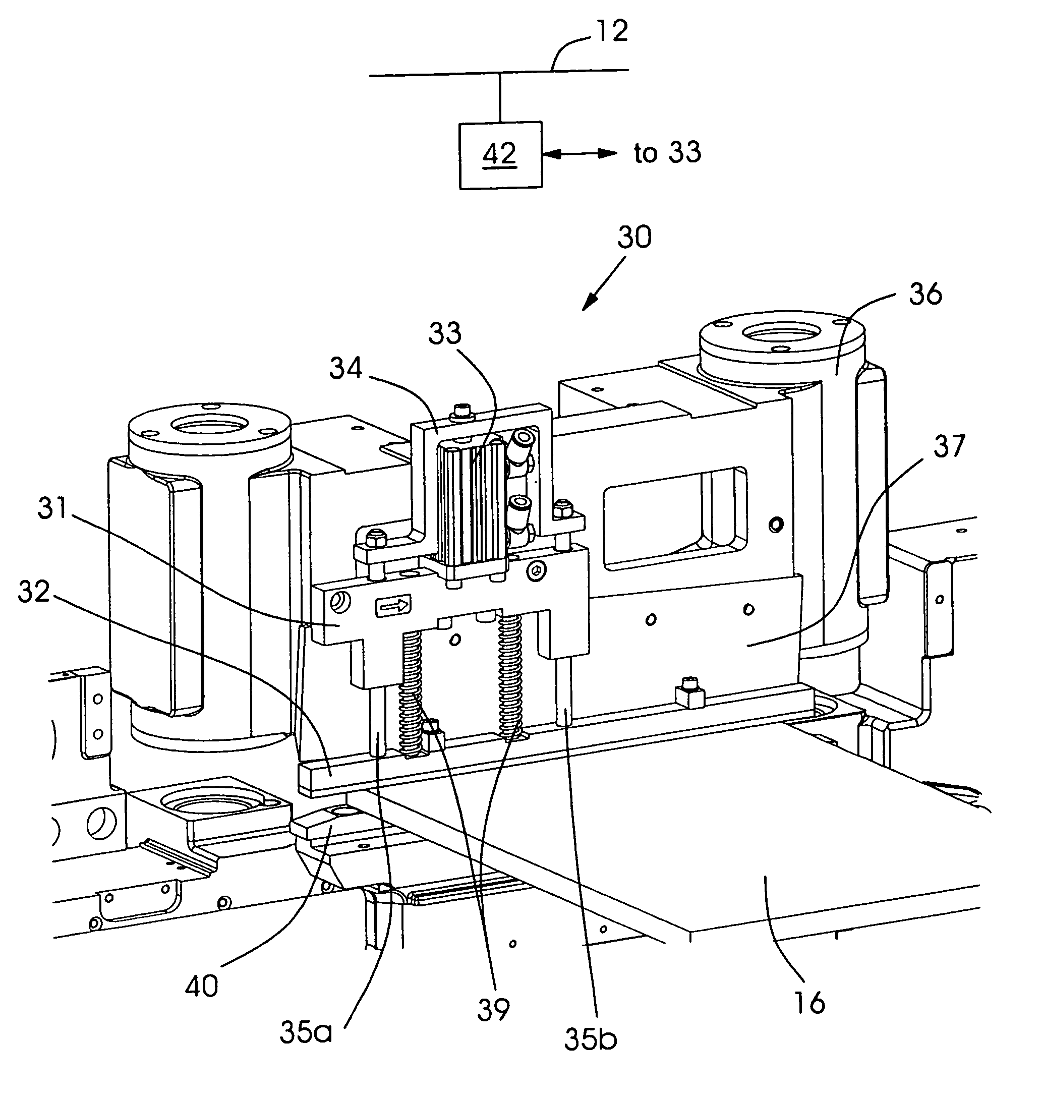
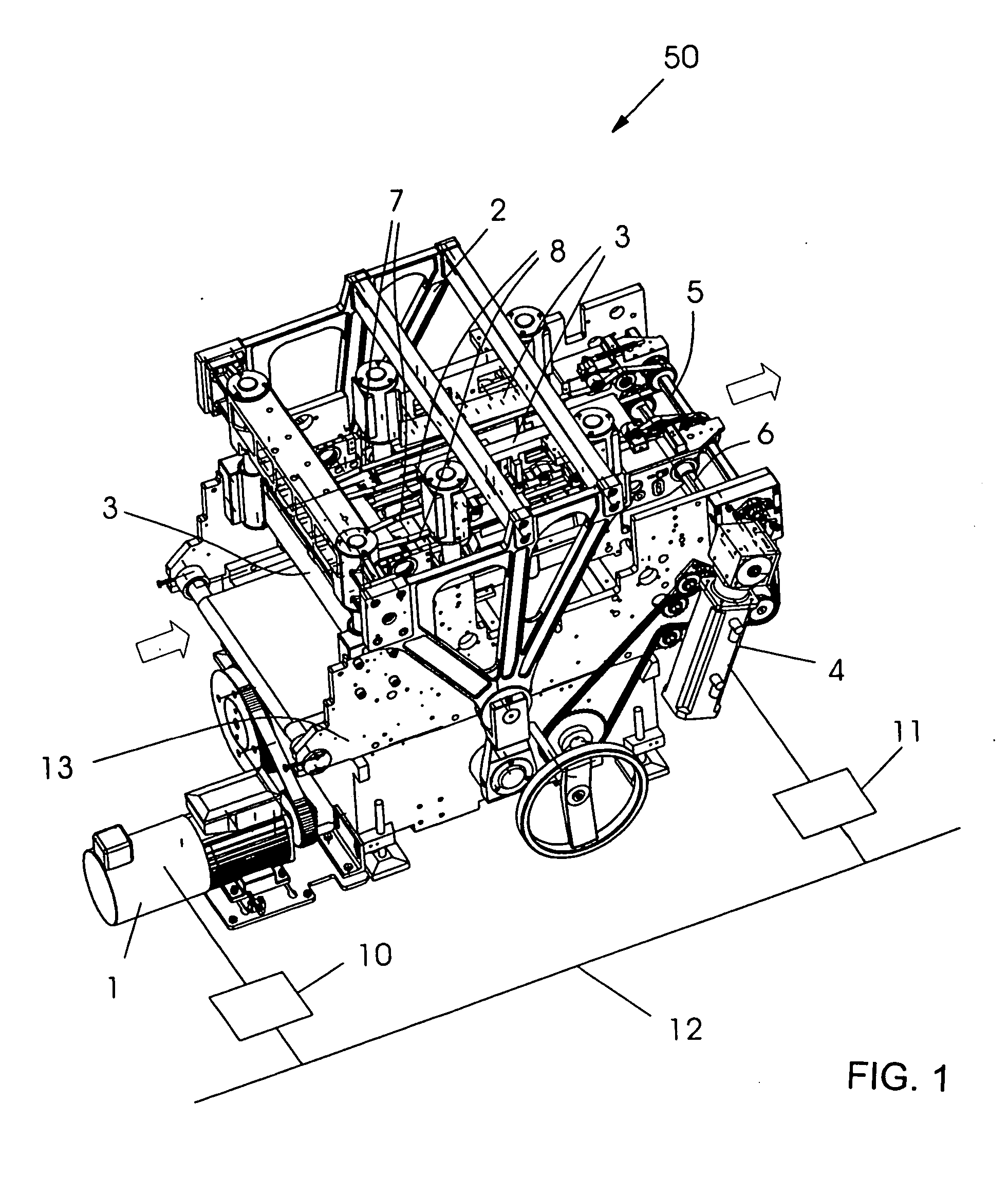
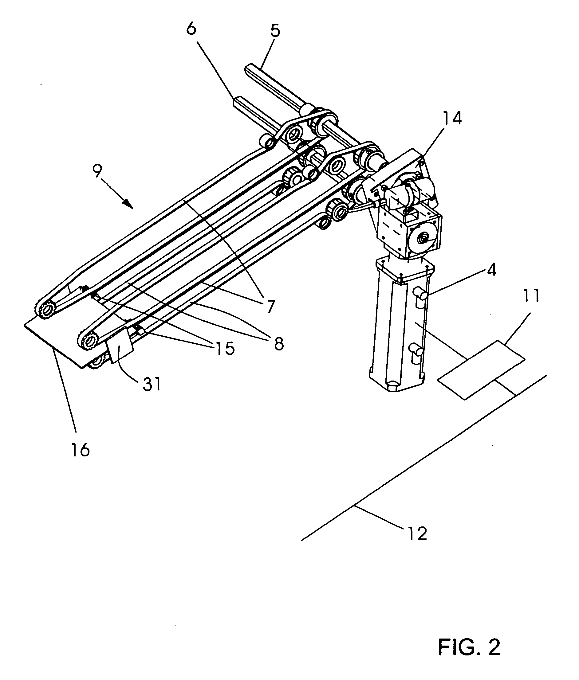
[0016] Referring now to the figures of the drawings in detail and first, particularly, to FIG. 1 thereof, there is seen a representative example of a cutting device 50 for the three-sided cropping of products. A first drive motor 1 executes movement of a knife lifting configuration 2 to which knives 3 are fastened. A product running direction is identified by arrows. A second drive motor 4 drives belts 7, 8 of a transport configuration 9, shown in greater detail in FIG. 2, through first and second drive shafts 5, 6. Control units 10, 11 which are provided for the two drive motors 1, 4 can communicate with one another through the use of a connection 12 for the exchange of data and / or control signals. Furthermore, the connection 12 may also lead to a machine control unit and to a control of an alignment configuration 42 shown in FIG. 3.

[0017]FIG. 2 separately illustrates the transport configuration 9. The drive motor 4 drives the drive shafts 5 and 6 and the belts 7, 8 of the transpo...


PUM

PropertyMeasurementUnit
widthaaaaaaaaaa
thicknessaaaaaaaaaa
speedaaaaaaaaaa

Abstract

A device for the three-sided cropping of products, includes a lifting configuration constructed for operating in a stroke movement determining a machine cycle of the device. At least knives for head cropping, foot cropping and front edge cropping of the products are to be mounted on the lifting configuration. A pressing device presses the products before cropping. A device terminates the pressing of the pressing device, in such a way that the pressing duration of the device can be varied.

Description

CROSS REFERENCE TO RELATED APPLICATIONS [0001] This application claims the priority, under 35 U.S.C. § 119(e), of Provisional Patent Application No. 60 / 713,485 filed Sep. 1, 2005. This application also claims the priority, under 35 U.S.C. § 119, of German Patent Application DE 10 2005 040 799.4, filed Aug. 29, 2005; the prior applications are herewith incorporated by reference in their entirety.BACKGROUND OF THE INVENTION Field of the Invention [0002] The invention relates to a device for the three-sided cropping of products, in particular brochures. The device includes a lifting configuration constructed to be operable in a stroke movement. The stroke movement determines a machine cycle of the device. At least knives for head cropping, foot cropping and front edge cropping of the products can be mounted on the lifting configuration. The device has a pressing device for pressing the products before cropping. [0003] In the production of brochures, gathered and stitched products are c...

Claims


Application Information

Patent Timeline
01 Mar 2007
Publication
US20070044616A1
IPC
B26D5/08
CPC
B26D1/09; B26D7/025; B26D2007/0081; Y10T83/8821
Inventors
MATTHES, WOLFGANG; STEINERT, ANDREAS