Pilot controlled pulse valve

Inactive Publication Date: 2007-03-01
FESTO AG & CO KG
View PDF14 Cites 2 Cited by
  • Summary
  • Abstract
  • Description
  • Claims
  • Application Information

AI Technical Summary

Benefits of technology

[0006] One object of the present invention is to provide measures in a pilot controlled pulse valve ensuring a low-wear fixation of the valve spool in the respective terminal position and furthermore able be put into practice at low costs.
[0008] The principle of functioning of the latching means in accordance with the invention based on magnetic force renders possible minimized wear operation and ensures a long service life of the pulse valve without any substantial reduction in the latching forces. The impact of the valve spool on reaching its terminal position is absorbed by an abutment means independent of the permanent magnet means and is imparted to the valve housing bypassing the permanent magnet means so that the permanent magnet means is hardly subjected to any mechanical load and accordingly a risk of being damaged or crushed. Since the axial intermediate space, present in the terminal position between the valve spool and the permanent magnet means, is free of ferromagnetic material, by way of the change in the axial distance apart the magnetic latching forces acting on the valve spool may be influenced, more particularly taking into account the control pressure acting during operation on the valve spool. It is therefore possible, if necessary using one and the same permanent magnet means to produce different levels of magnetic latching forces in accordance with the type of valve by changing the said axial distance apart.

Problems solved by technology

Since the seals are subject to wear in the course of time such latching in the terminal position can not be ensured permanently.
Alternatively it would also be possible to employ latching means designed as detent means in the case of which however there would also be a wear problem.
Since accordingly the terminal impact of the valve member directly acts on the permanent magnet, such an arrangement is not appropriate for use in pulse valves, since in this case the valve spool must be displaced a fair distance between its two terminal positions and therefore on arriving in the terminal position has a large amount of kinetic energy, something which could damage the permanent magnet.
Moreover, as in the case of the said European patent publication 0 650 002 B1 the magnetic holding force may only be influenced by the employment of permanent magnet means of different strength, something rendering it a relatively complex task to provide spool valves with different actuating forces, since it is necessary to have recourse to different permanent magnet means.

Method used


Image

  • Pilot controlled pulse valve
  • Pilot controlled pulse valve

Examples


Embodiment Construction

.

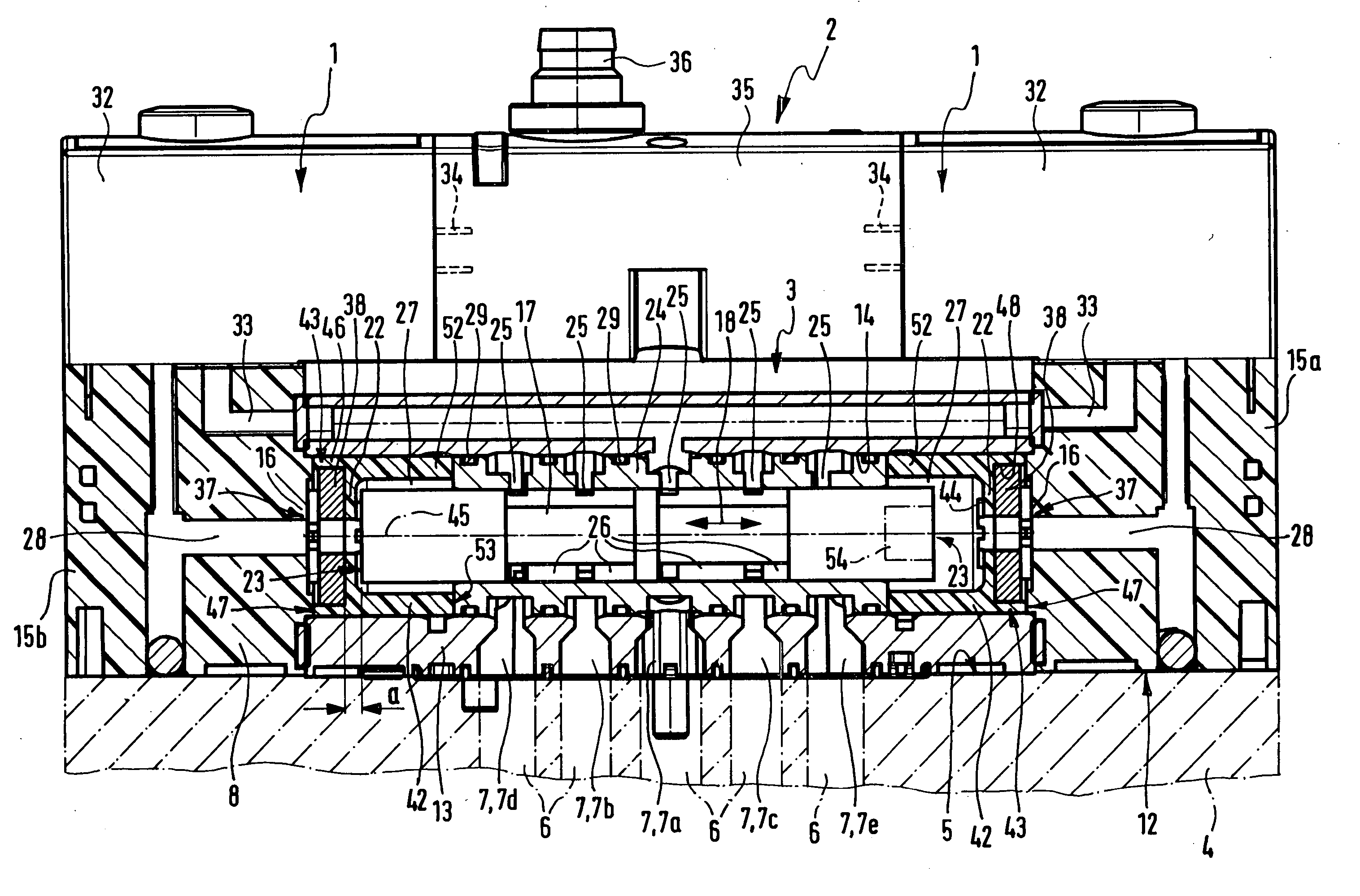
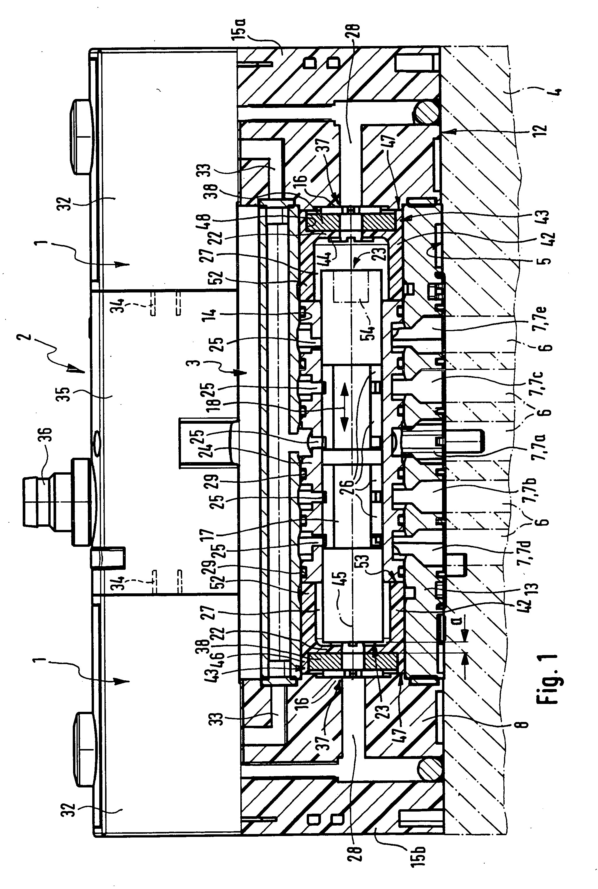
[0021] The drawing shows a pulse valve 2 which is pilot controlled by means of an electrically actuated pilot control means 1, comprising a principal fluid operated valve 3 by way of the pilot valve means 1, such principal valve 3 being assembled together with the pilot valve means 1 in the form of a uniformly handled sub-assembly.

[0022] The pulse valve 2 is mounted on a base plate 4 indicated in chained lines. At the corresponding component mounting face 5 of the base plate 4 base plate ducts 6 open, which communicate with flush valve ducts 7 extending in the valve housing 8 of the principal valve 3 and open opposite to the base plate ducts 6 at the mounting face 12, of the valve housing 8.

[0023] The valve housing 8 of the working example comprises an elongated middle part 13, which exhibits a cavity extending through in the longitudinal direction and which serves as a valve spool socket 14. At the end on either side of the middle part 13 a respective terminal part 15a and 15b i...


PUM


Abstract

A pilot controlled pulse valve has a valve spool releaseably held in both terminal positions by latching means. The latching means comprise a permanent magnet means holding the valve spool by magnetic force. To set the terminal or end position the permanent magnet means has an abutment means placed to the fore of it. In order to protect the permanent magnet means against damage the abutment means bears against the valve housing independently of the permanent magnet means.

Description

BACKGROUND OF THE INVENTION [0001] The invention relates to a pilot controlled pulse valve comprising a principal valve which is able to be fluid actuated by a pilot valve means and which possesses a valve spool able to be switched over between two terminal positions by pulsed fluid actuation in a valve housing, at least one axial terminal portion of the valve spool possessing holding means for releasable housing-related latching of the valve spool when in a terminal position and not axially fluid-actuated. [0002] Pulse valves are multiway valves, whose valve spools are actuated by a fluid control pressure in a pulsed manner for switching over between two terminal positions, the valve spool maintaining its terminal position even after termination of the control pressure. Such valves exhibit the advantage that the switching positions of the valve spool may be maintained for a practically unlimited time without the constant supply of energy. In order to ensure that the valve spool dwe...

Claims


Application Information

Patent Timeline
IPC IPC(8): F15B13/043
CPCF15B13/0402F15B13/0431F16K11/0704F16K31/426Y10T137/86614Y10T137/8663F16K31/08
Inventor RAPKE, FALKBOGDANOWICZ, GRZEGORZ
Owner FESTO AG & CO KG
Why Eureka
Try Eureka