
Methods, systems and apparatus for coiled tubing testing

a technology of coiled tubing and testing methods, applied in the direction of drilling casings, drilling pipes, surveying, etc., can solve the problems of requiring removal of existing completions, unable to collect real-time data during the testing operation, and the drilling-stem testing does not lend itself to real-time data collection

Inactive Publication Date: 2007-03-01
SCHLUMBERGER TECH CORP
View PDF25 Cites 68 Cited by
  • Summary
  • Abstract
  • Description
  • Claims
  • Application Information

AI Technical Summary

Benefits of technology

The present invention provides a method and apparatus for testing a multi-zone reservoir while reservoir fluids are flowing from within a wellbore. This allows for the isolation and measurement of fluid flow and pressure from each individual zone, providing valuable information on the reservoir's performance. The technical effects include improved wellbore testing and evaluation of reservoir performance, leading to more efficient oil and gas production.

Problems solved by technology

Problems arise because of commingled flow.
Unfortunately, drill-stem testing requires removing existing completions, and includes the cost of bringing a rig to convey individual sections of drillpipe.
Drill-stem testing also does not lend itself to real-time data collection during the testing operation.
Wireline testing includes the necessity to kill the well to convey the wireline tool, which is undesirable, and the short interval that can be tested is frequently unsatisfactory.
The weight and cost of the concentric coiled tubing limits commercial application.

Method used


Image

  • Methods, systems and apparatus for coiled tubing testing
  • Methods, systems and apparatus for coiled tubing testing
  • Methods, systems and apparatus for coiled tubing testing

Examples


Embodiment Construction

[0030] In the following description, numerous details are set forth to provide an understanding of the present invention. However, it may be understood by those skilled in the art that the present invention may be practiced without these details and that numerous variations or modifications from the described embodiments may be possible.

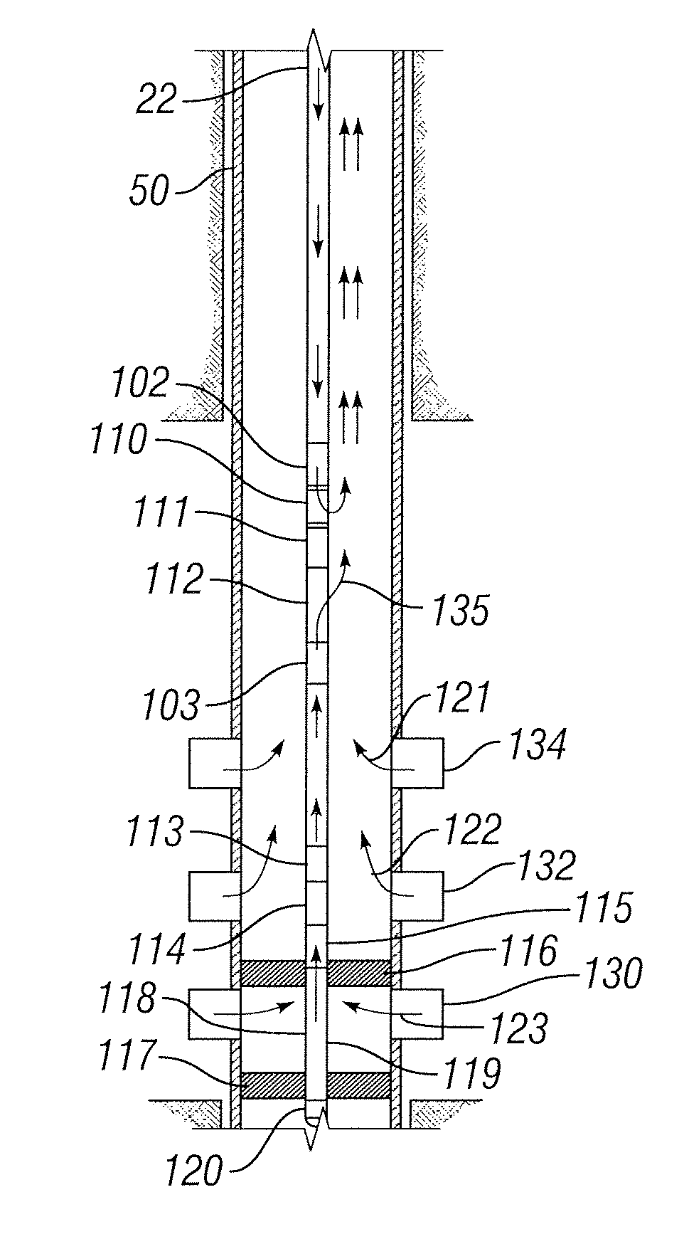
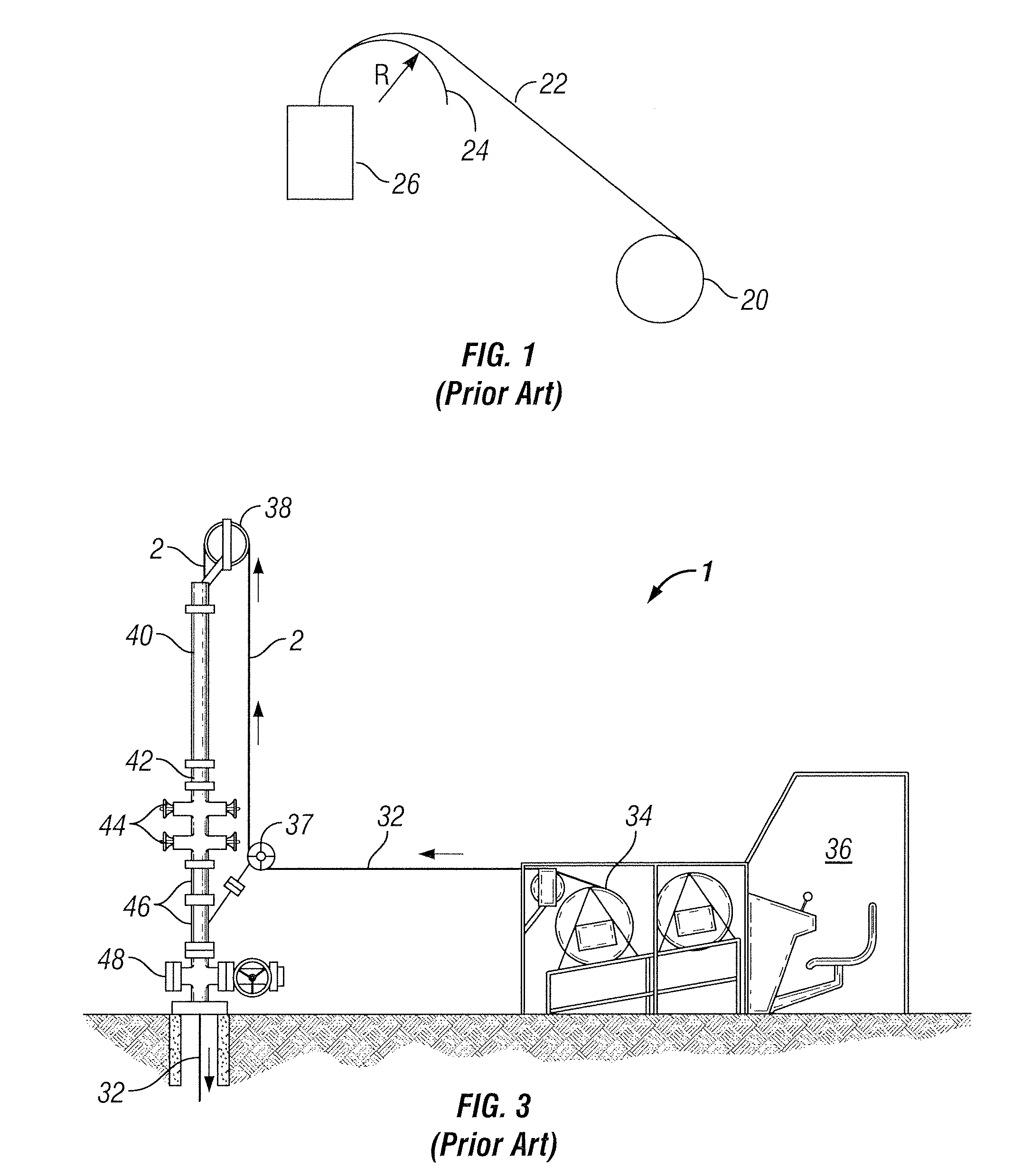
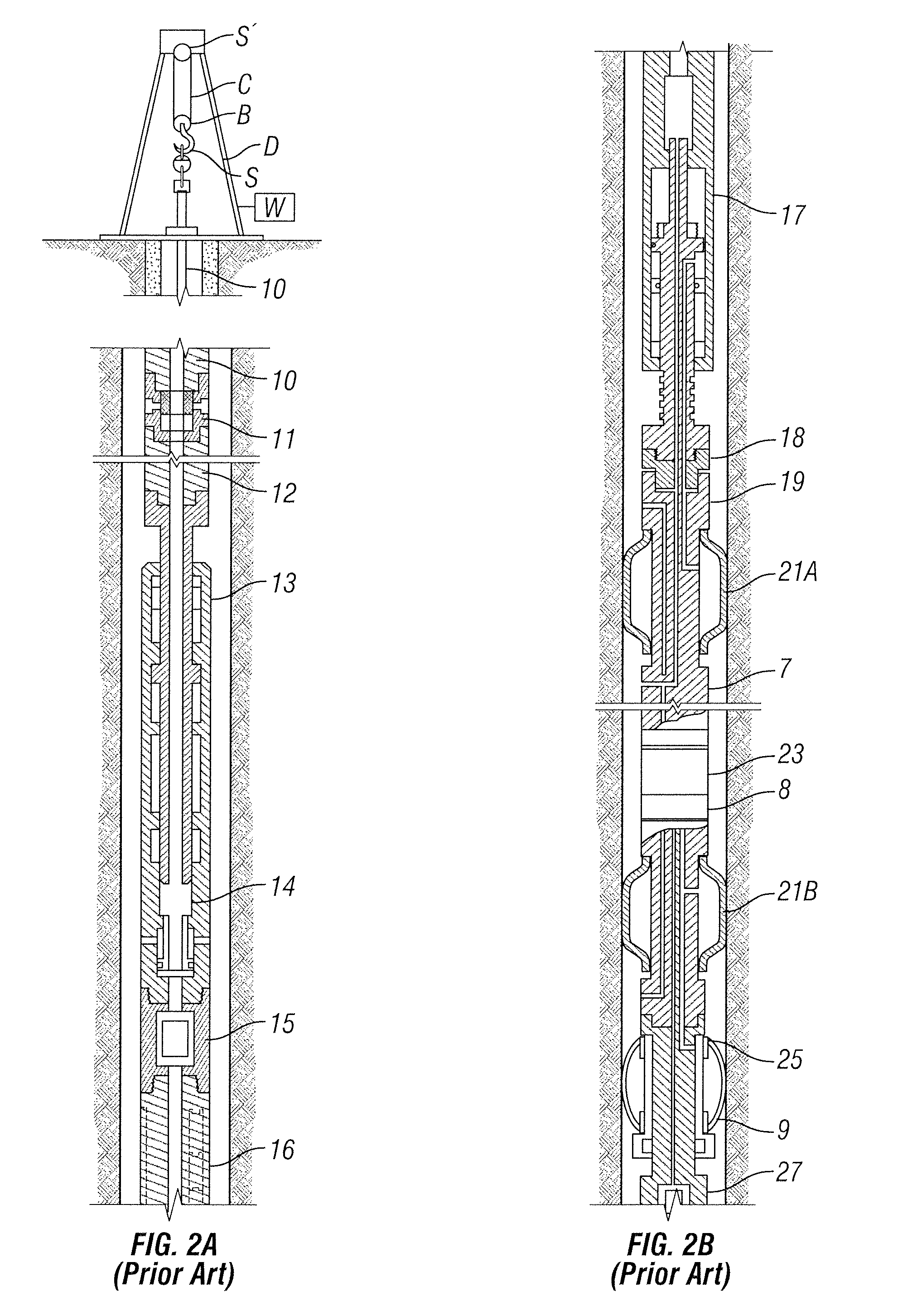
[0031] By “wellbore”, we mean the innermost tubular of the completion system. “Surface”, unless otherwise noted, means very generally out of the wellbore, above or at ground level, and generally at the well site, although other geographic locations above or at ground level may be included. “Tubular” and “tubing” refer to a conduit or any kind of a round hollow apparatus in general, and in the area of oilfield applications to casing, drill pipe, metal tube, or coiled tubing or other such apparatus. By “well servicing”, we mean any operation designed to increase hydrocarbon recovery from a reservoir, reduce non-hydrocarbon recovery (when non-hydrocarb...


PUM


Abstract

A method and apparatus for testing a multi-zone reservoir while reservoir fluids are flowing from within the wellbore. The method and apparatus enables isolation and testing of individual zones without the need to pull production tubing. This abstract allows a searcher or other reader to quickly ascertain the subject matter of the disclosure. It may not be used to interpret or limit the scope or meaning of the claims.

Description

CROSS-REFERENCE TO RELATED APPLICATIONS [0001] The present application claims priority under 35 U.S.C. § 119(e) to U.S. Provisional Application Ser. No. 60 / 713,570, filed Sep. 1, 2005, incorporated by reference herein in its entirety.BACKGROUND OF THE INVENTION [0002] 1. Field of Invention [0003] The present invention relates generally to the field of testing hydrocarbon-bearing formations, and more particularly to methods, systems and apparatus useful in such operations. [0004] 2. Related Art [0005] Coiled tubing is a technology that has been expanding its range of application since its introduction to the oil industry in the 1960's. Its ability to pass through completion tubulars and the wide array of tools and technologies that can be used in conjunction with it make it a very versatile technology, and this versatility is the core of this invention. Recent advances in coiled tubing allow real-time control of downhole equipment, transmission of measurement data and isolation of in...

Claims


Application Information

Patent Timeline
Patent Type & Authority Applications(United States)
IPC IPC(8): E21B47/06
CPCE21B17/206E21B33/124E21B49/087E21B43/122E21B49/008E21B34/06E21B49/08
Inventor LOVELL, JOHN R.ZEMLAK, WARRENALLCORN, MARCPEIXOTO, LUIS F.HARRISON, STEVENPRESTRIDGE, ANDREWTUNC, GOKTURKESPINOSA, FRANK
Owner SCHLUMBERGER TECH CORP
Learn More