
Systems and methods for locating and controlling powered vehicles

a technology for locating and controlling powered vehicles, applied in the direction of pedestrian/occupant safety arrangements, anti-theft devices, tractors, etc., can solve the problems of creating a safety hazard for other customers and vehicles, and inconvenient cart retrieval

Active Publication Date: 2007-03-01
GATEKEEPER SYST
View PDF46 Cites 32 Cited by
  • Summary
  • Abstract
  • Description
  • Claims
  • Application Information

AI Technical Summary

Benefits of technology

[0009] Another embodiment of a system for localizing and controlling movement of a personal mobility vehicle is described. The system comprises a signal source configured to transmit a localization signal. The signal source is further configured to be disposed on a personal mobility vehicle. The system also comprises at least one detector configured to receive the localization signal and to determine a direction of the signal source relative to the detector. The system includes a control unit configured to communicate with the at least one detector and to determine a localization of the signal source relative to the at least one detector. The control unit is further configured to use the localization of the source to determine whether to provide a command to control a motor on the personal mobility vehicle. In one embodiment, a personal mobility vehicle comprises the system.
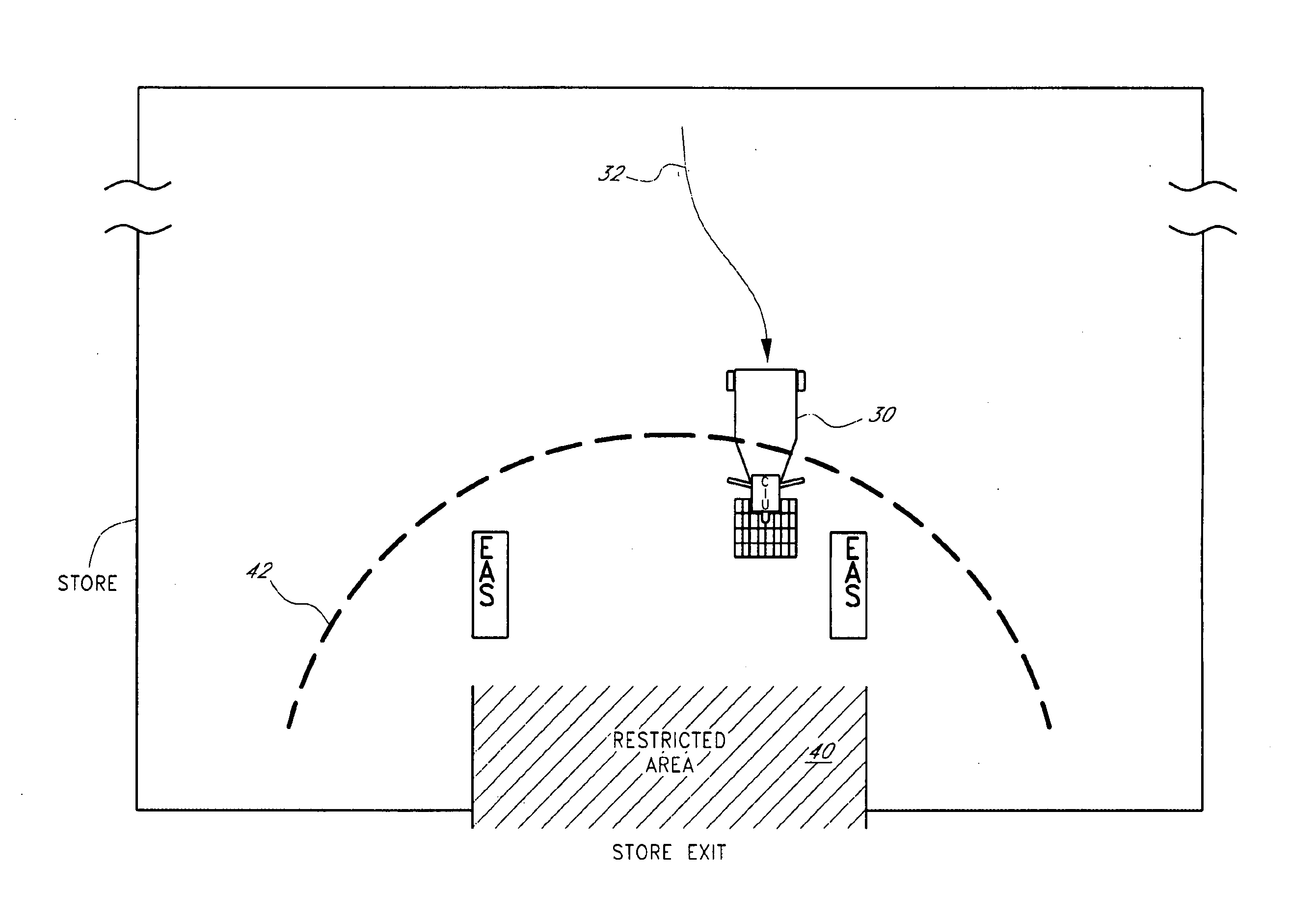
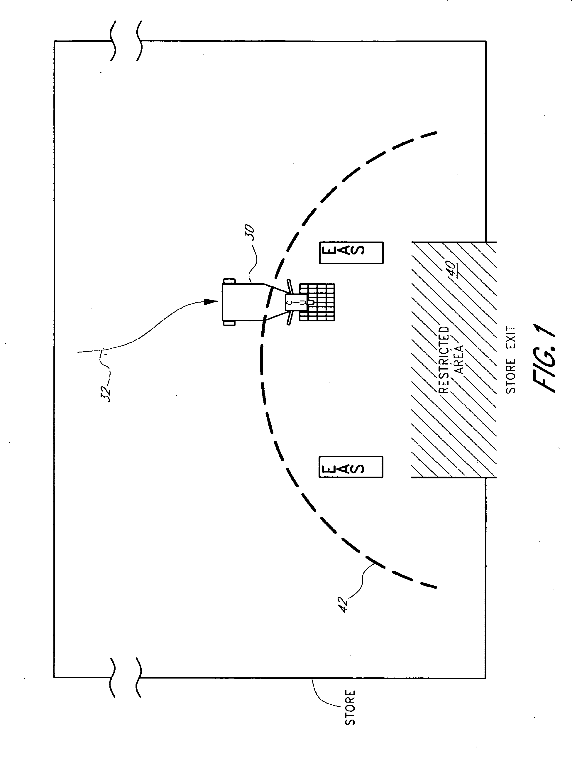
[0010] An embodiment of a processor-implemented method of inhibiting a personal mobility vehicle from entering a restricted region is disclosed. The method comprises determining a location of a personal mobility vehicle relative to a limit line near a restricted region and determining a direction of travel of the personal mobility vehicle relative to the limit line. The method further comprises making a decision, with a processor, whether to inhibit motion of the personal mobility vehicle into the restricted region. The processor is configured to use information related to at least one of the location and the direction of travel of the personal mobility vehicle. The method also comprises inhibiting motion of the personal mobility vehicle in response to the decision made with the processor.
[0011] In one aspect of the disclosure, a system for inhibiting a personal mobility vehicle from entering a restricted region comprises means for determining a location of a personal mobility vehicle relative to a limit line near a restricted region and means for determining a direction of travel of the personal mobility vehicle relative to the limit line. The system further comprises means for making a decision whether to inhibit motion of the personal mobility vehicle into the restricted region, the decision means using information related to at least one of the location and the direction of travel of the personal mobility vehicle and means for inhibiting motion of the personal mobility vehicle in response to the decision.
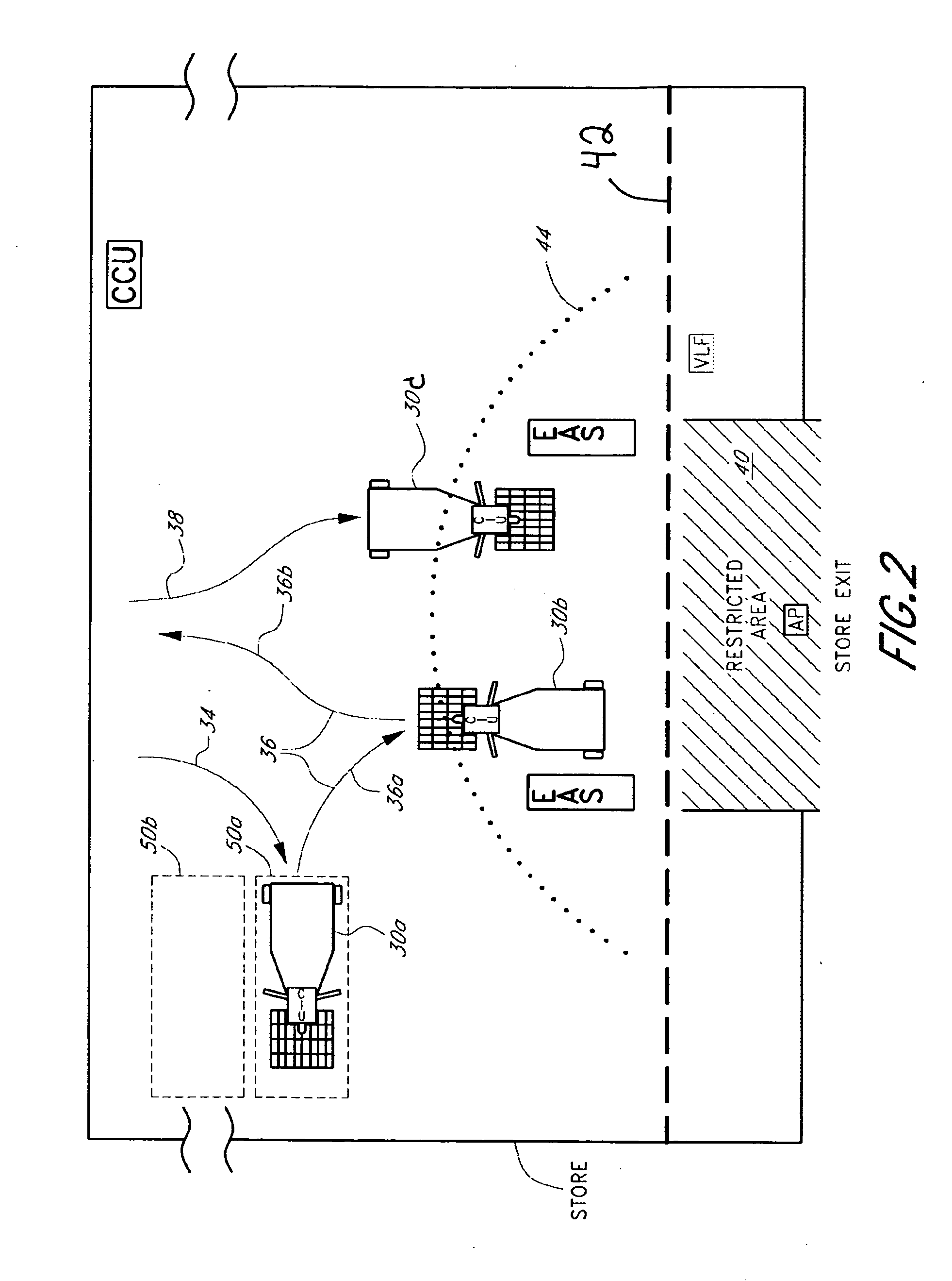
[0012] An embodiment of a processor-implemented method of controlling a personal mobility vehicle near a restricted region is described. The method comprises determining a first location of a personal mobility vehicle relative to a first limit line near a restricted region and determining a first direction of travel of the personal mobility vehicle relative to the first limit line. The method further comprises providing a warning if the first location and the first direction of travel indicate the personal mobility vehicle is approaching the restricted region. The method also comprises determining a second location of the personal mobility vehicle relative to a second limit line. The second limit line is closer to the restricted region than the first limit line. The method further comprises determining a second direction of travel of the personal mobility vehicle relative to the second limit line and inhibiting motion of the personal mobility vehicle if a processor determines, using at least one of the second location and the second direction of travel, that the personal mobility vehicle is approaching the restricted region.
[0013] In another aspect of the disclosure, a system for localizing and controlling movement of a personal mobility vehicle comprises a signal source configured to transmit a localization signal. The signal source is further configured to be disposed on a personal mobility vehicle. The system further comprises two detectors configured to receive the localization signal. The two detectors define a first limit line therebetween. The system also comprises a control unit configured to communicate with the two detectors and to determine a first localization of the signal source relative to the first limit and a second localization of the signal source relative to a second limit line.
[0014] In another aspect of the disclosure, a system for controlling a personal mobility vehicle near a restricted region comprises means for determining a first location of a personal mobility vehicle relative to a first limit line near a restricted region and means for determining a first direction of travel of the personal mobility vehicle relative to the first limit line. The system also comprises means for providing a warning if the first location and the first direction of travel indicate the personal mobility vehicle is approaching the restricted region. The system further comprises means for determining a second location of the personal mobility vehicle relative to a second limit line, where the second limit line is closer to the restricted region than the first limit line. The system also includes means for determining a second direction of travel of the personal mobility vehicle relative to the second limit line and means for determining, using at least one of the second location and the second direction of travel, whether the personal mobility vehicle is approaching the restricted region. The system also comprises means for inhibiting motion of the personal mobility vehicle, wherein the inhibiting means are configured to be actuated in response to the determination by the determining means.

Problems solved by technology

However, stores may wish to restrict movement of carts into areas that are unsafe or inconvenient for cart retrieval and to deter theft and reduce other types of cart misuse.
For example, a customer who drives a powered cart in a store parking lot may create a safety hazard for other customers and vehicles.
Also, the customer may leave the cart at a location that blocks pedestrian access paths or vehicle parking spaces or at a location that makes cart retrieval inconvenient.

Method used


Image

  • Systems and methods for locating and controlling powered vehicles
  • Systems and methods for locating and controlling powered vehicles
  • Systems and methods for locating and controlling powered vehicles

Examples


Embodiment Construction

I. Overview

[0025] Certain specific embodiments of the invention will now be described in detail with reference to the drawings listed above. These drawings and description of the disclosed embodiments are presented by way of example only, and do not limit the scope of the invention, which extends to alternative embodiments and uses of the invention and to obvious modifications and equivalents thereof. Thus, the scope of the invention is not to be limited to the preferred embodiments described below but is defined by the claims. For example, in any method or process described herein, the acts or operations of the method / process are not necessarily limited to any particular disclosed sequence. Also, for purposes of contrasting different embodiments or the prior art, certain aspects and advantages of these embodiments are described herein where appropriate. It should be understood that not necessarily all such aspects and advantages need be achieved in any one embodiment. Thus, it shou...


PUM


Abstract

A system for controlling movement of a personal mobility vehicle near a restricted region is disclosed. In one embodiment, the system includes a detector that is configured to be disposed on the personal mobility vehicle and that is configured to receive an electromagnetic signal transmitted to the restricted region. The system also includes a control unit configured to communicate with the detector. The control unit is further configured to determine proximity of the detector to the restricted region using information related to the signal received by the detector. The control unit is also configured to provide a command to inhibit movement of the personal mobility vehicle in response to the determined proximity of the vehicle to the restricted region.

Description

RELATED APPLICATIONS [0001] This application claims the benefit under 35 U.S.C. § 119(e) of U.S. Provisional Application Ser. No. 60 / 711,135, filed Aug. 25, 2005, titled “MOBILITY CART CONTAINMENT SYSTEM AND METHODS,” which is hereby incorporated by reference herein in its entirety.BACKGROUND OF THE DISCLOSURE [0002] 1. Field [0003] The present disclosure relates to systems and methods for determining the location and controlling the movement of powered vehicles, including but not limited to electric-powered, motorized carts. [0004] 2. Description of the Related Art [0005] Retail stores may provide powered shopping carts for the convenience of their customers. For example, some powered shopping carts include a seat for a customer, a basket to hold retail goods, and a battery-powered electric motor system that allows the customer to travel within the retail store. Motorized shopping carts can be used in many commercial or retail environments. For example, motorized carts may be provi...

Claims


Application Information

Patent Timeline
Patent Type & Authority Applications(United States)
IPC IPC(8): B60T7/16
CPCB60T7/16
Inventor CARTER, SCOTT J.JAMES, JESSE M.HANNAH, STEPHEN E.
Owner GATEKEEPER SYST
Learn More