
Single cup coffee container holder

a coffee container and single cup technology, applied in the direction of revolving cabinets, show hangers, cabinets, etc., can solve the problems of difficult for consumers to choose the label of their choice, unused beverage cartridges, and cluttered cups and counters, etc., to achieve the effect of being observed quickly

Inactive Publication Date: 2007-03-01
NIFTY HOME PROD
View PDF6 Cites 47 Cited by
  • Summary
  • Abstract
  • Description
  • Claims
  • Application Information

AI Technical Summary

Benefits of technology

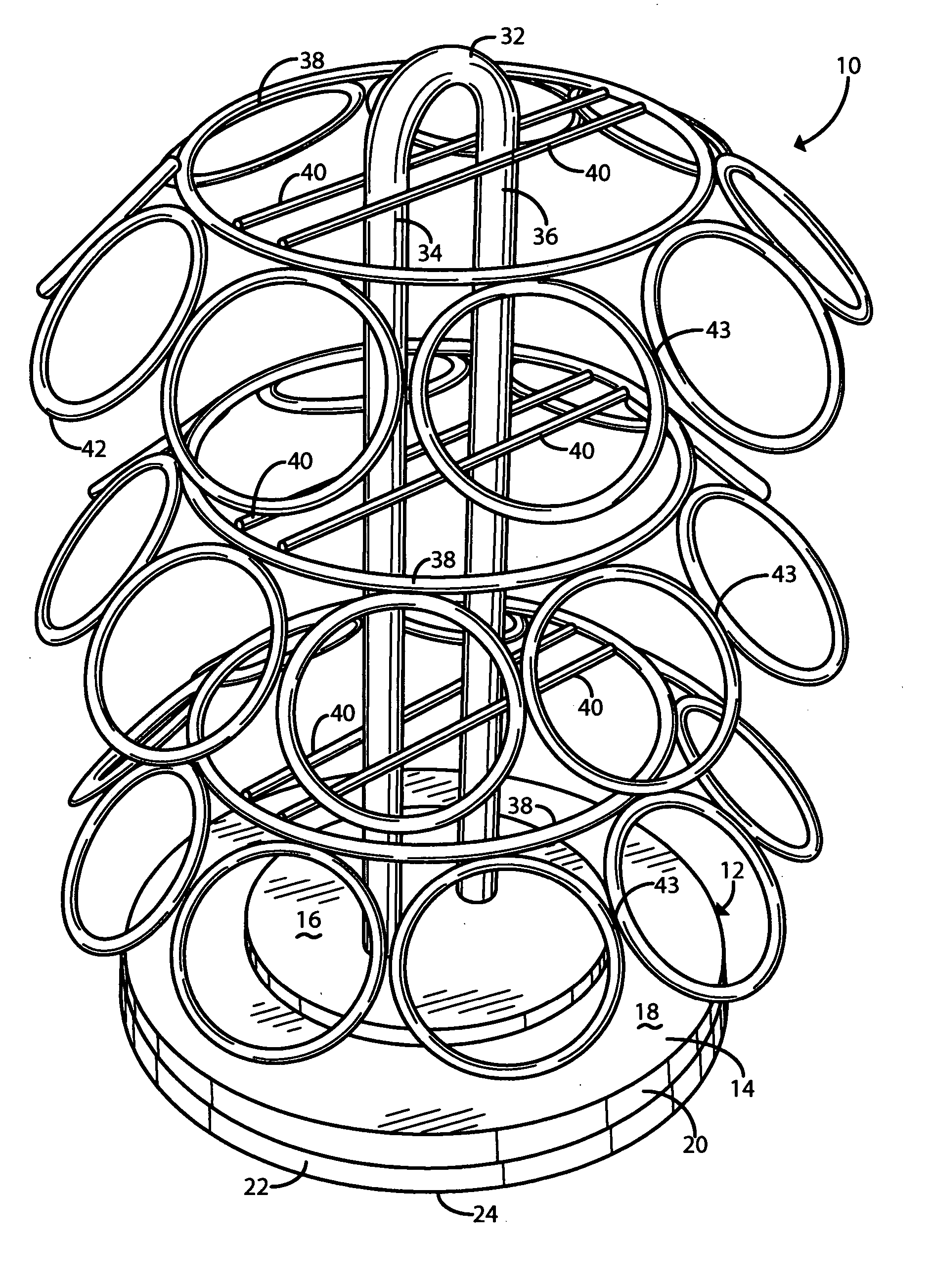
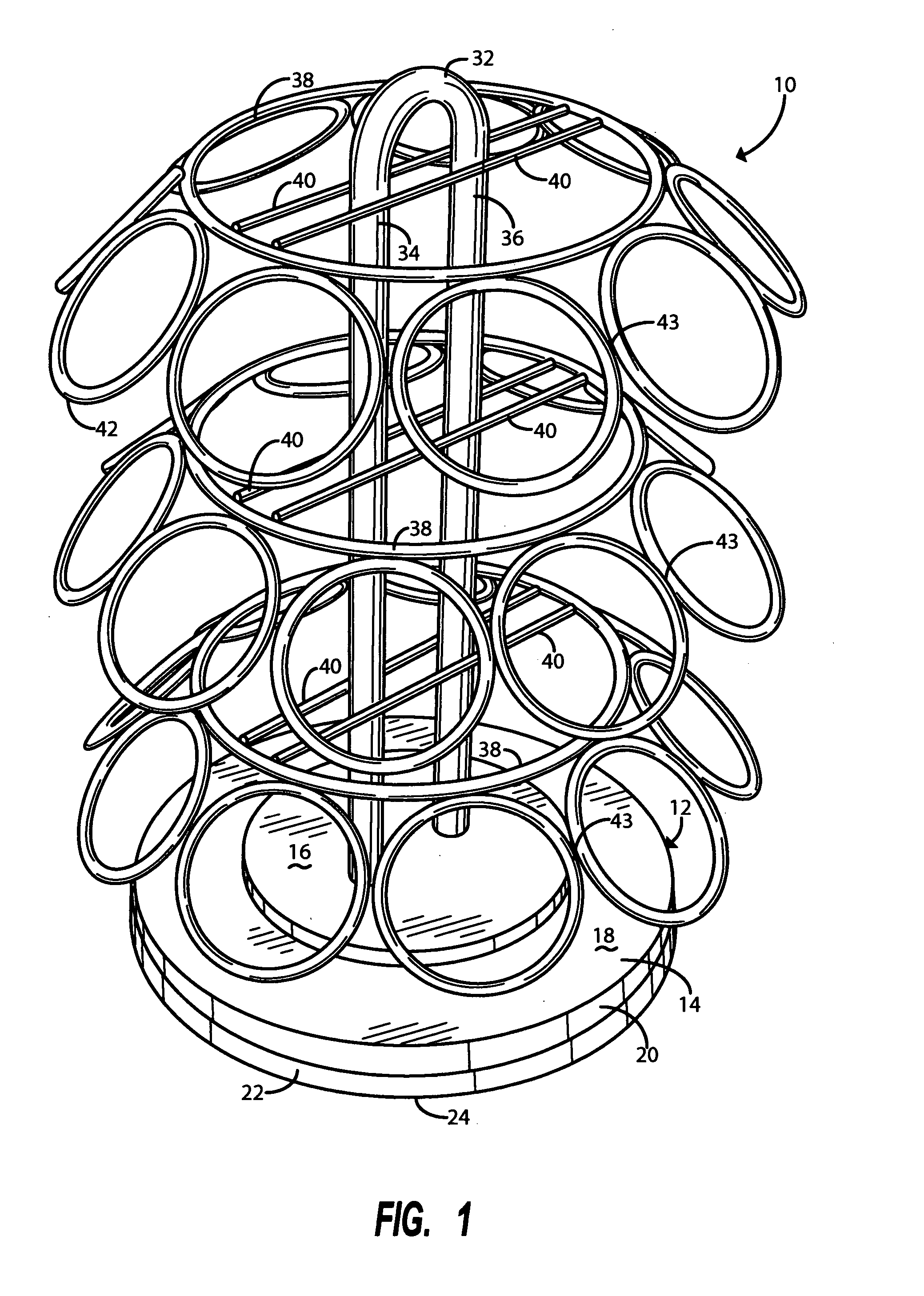
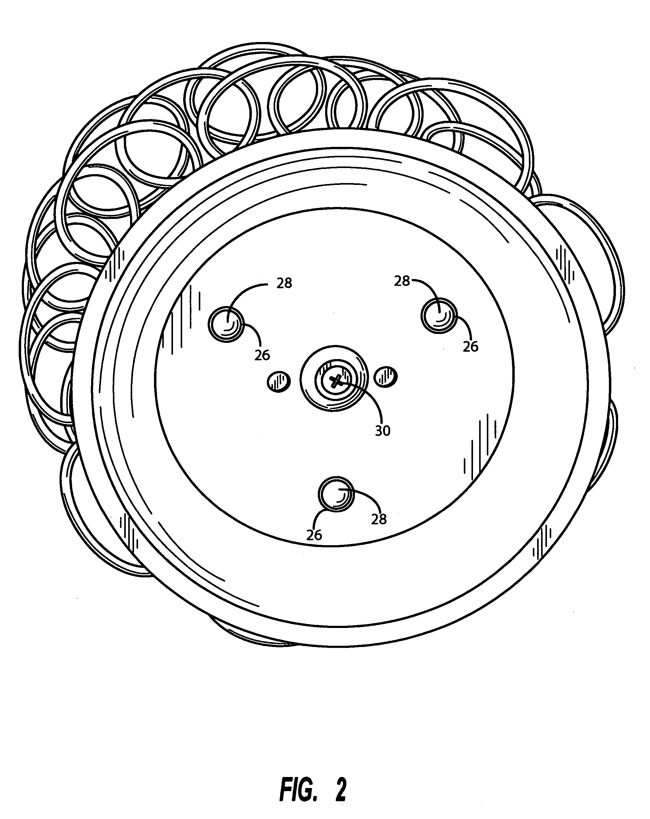
[0009] In accordance with one embodiment of the invention, the base member has a stationary annular segment and an inner plate segment. Said stationary annular segment has a diameter larger than the diameter of the inner plate. Said inner plate is rotatably secured to the stationary annular segment. The vertical stand is secured to the inner plate such that when the inner plate is rotated, the stand rotates with it. The spaced-apart hoops encircle the stand and have two parallel bars extending the diameter of the hoops. The stand then extends between the parallel bars of each hoop at the center point of each hoop, and the parallel bars are secured to the stand at three different positions along the length of the stand. The hoops each have a plurality of tangentially coupled ring members. The ring members are each sized to retain a beverage filter cartridge wherein the container is inserted into the ring and the peripheral rim of the cartridge interferes with the ring so that the cartridge hangs in the ring. Because the rings attach to the hoop at an oblique angle, the labels on the lids of the cartridges are readily observed.

Problems solved by technology

However, because single-cup brewers give consumers so many options, cupboards and counters may become cluttered with different, unused beverage cartridges.
Therefore, stacking the containers on top of each other would cover the label and make it difficult for the consumer to choose the label of her choice.

Method used


Image

  • Single cup coffee container holder
  • Single cup coffee container holder
  • Single cup coffee container holder

Examples


Embodiment Construction

[0018] Referring now to the drawings, there is shown in the perspective view of FIG. 1 a rack designated generally as reference numeral 10 constructed in accordance with one embodiment of the present invention. The rack 10 is constructed of metal with chrome plating. By way of example only, it may have an overall width of approximately 7⅜ inches and overall height of approximately 10 inches. Because of its relatively compact size, the rack can easily fit in either a cupboard or on a kitchen counter. It is understood that the rack 10 may be formed of different sufficiently rigid materials, and may be sized differently to hold more or less beverage filter cartridges.

[0019] The rack 10 includes a base member 12 comprising a stationary segment 14 and a rotatably mounted inner plate 16. The stationary segment 14 is sized to support the rack 10 so that it does not easily tip when fully loaded with beverage filter cartridges. Typically, the stationary segment 14 may have a 6 inch diameter...


PUM


Abstract

A rack adapted to retain a plurality of beverage filter cartridges including a rotatable base member, a stand extending vertically from the rotatable base member, a plurality of spaced-apart hoop members encircling the stand, and a plurality of ring members coupled tangentially to the hoop members and extending from the hoop members at an oblique angle. The base member further includes a stationary segment and an inner plate. The inner plate is rotatably secured to the stationary segment, and the stand projects vertically from the inner plate such that when the inner plate rotates, so does the stand. The spaced-apart hoop members encircle the stand and are supported by parallel bars that extend the diameter of the hoop members. The parallel bars are secured to the stand at different positions along the axis of the stand. The ring members are sized to retain a beverage filter cartridge, wherein a rim of the beverage filter cartridge hangs on the ring.

Description

FIELD OF THE INVENTION [0001] This invention relates to a rack adapted to retain disposable single-serve beverage filter cartridges. DESCRIPTION OF THE PRIOR ART [0002] In recent years, single-cup brewers have become popular in homes and offices. Singe-cup brewers brew fresh cups of coffee or tea in short periods of time. [0003] A disposable single-serve beverage filter cartridge, such as the ones shown in U.S. Pat. Nos. 5,325,765 and 5,840,189 (Sylvan et al.), dated respectively Jul. 5, 1994 and Nov. 24, 1998 are inserted into the brewer. During the brewing cycle, heated water is admitted into the cartridge for infusion with a beverage medium such as coffee grounds. All of the resulting brewed beverage is eventually poured into a waiting cup ready to be enjoyed. [0004] Such disposable single-serve beverage filter cartridges generally have an outer container with a bottom and side walls extending upwardly from the bottom to a peripheral rim surrounding the upper opening. A filter el...

Claims


Application Information

Patent Timeline
IPC IPC(8): A47B73/00
CPCA47B49/00A47B81/007A47J47/16A47F7/283A47J31/44A47F5/02
Inventor TIEMANN, FRANK R.
Owner NIFTY HOME PROD
Learn More