
Adjustable display resolution for thermostat

Active Publication Date: 2007-03-01
RANCO OF DELAWARE +1
View PDF25 Cites 18 Cited by
  • Summary
  • Abstract
  • Description
  • Claims
  • Application Information

AI Technical Summary

Benefits of technology

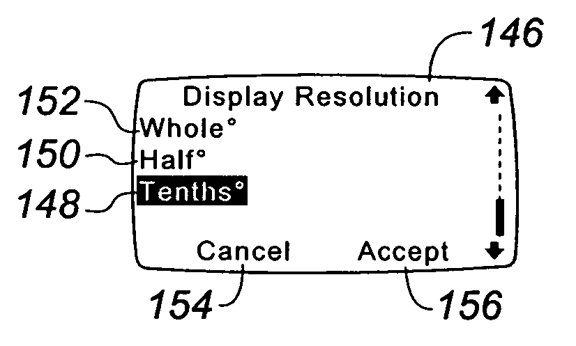
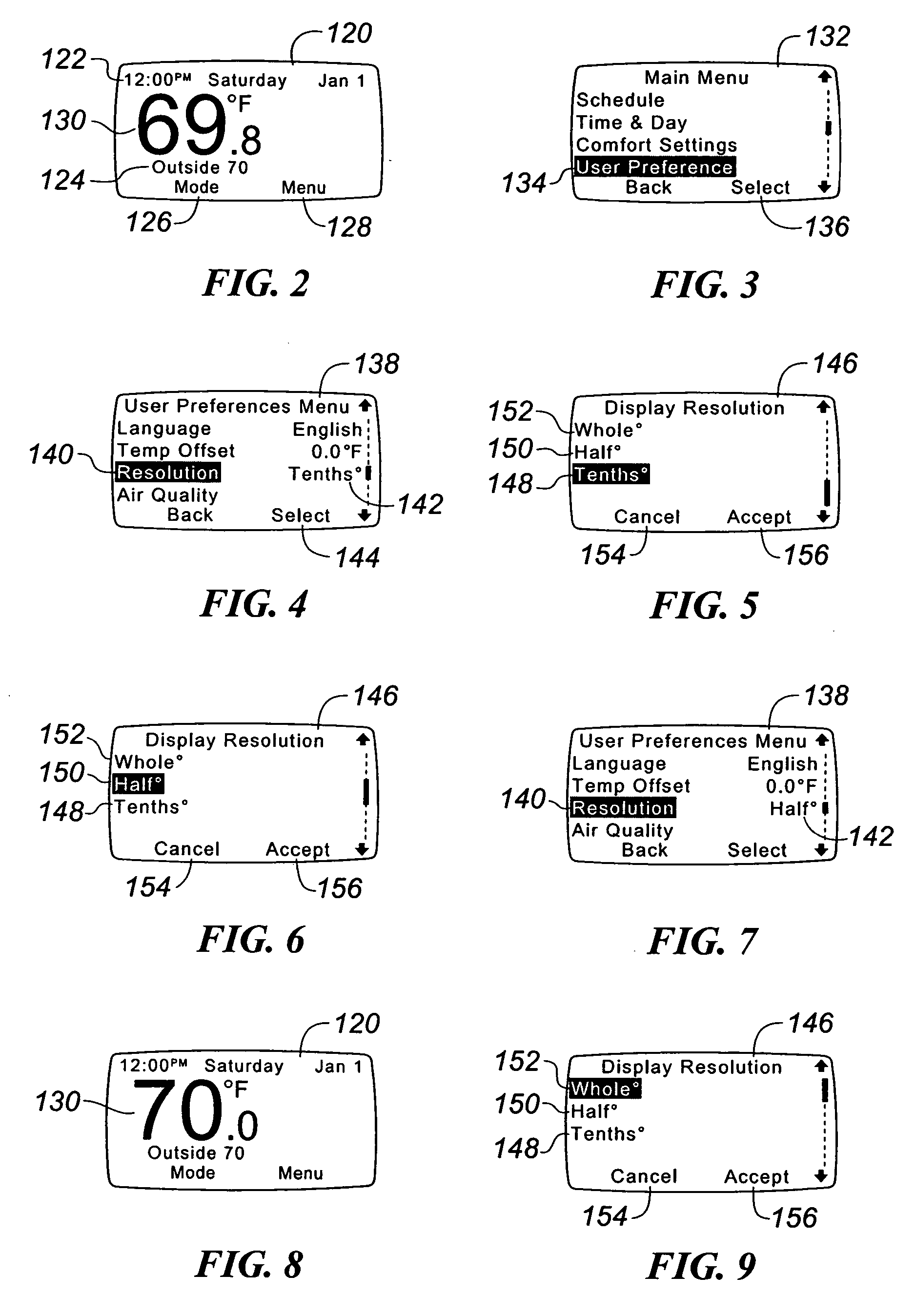
[0009] In one embodiment of the present invention, the adjustable resolution display system that allows the configuration of the display resolution at run time allows an OEM to ship units with the resolution configured to their liking, and also allows a customer to change it if they so desire. The ability to modify the display resolution can also be disabled in one embodiment to suit a particular OEM's requirements. Customers who do not care to have the finest resolution displayed can back off the resolution while the unit is installed, thus providing them with more control over their system.

Problems solved by technology

While the advances that are being included in modern digital thermostats greatly enhance the users' comfort level and minimize the energy usage, the overall user experience interfacing with such a digital thermostat has not kept pace.
However, such a thermostat, while perceived to be highly accurate due to the displayed resolution, may appear to be inaccurate when placed next to or compared with another temperature sensing device.
This often creates an issue for the original equipment manufacturer (OEM) customers of thermostats who receive numerous customer complaints about the accuracy of the digital thermostat.
However, this has lead to other complaints that such a sophisticated thermostat should be able to display finer resolution for the temperature readout.
Due to cost constraints, the thermostat manufactures only provide a single resolution for the same model of thermostat, with the resolution set to the lowest desired by all customers.
However, while addressing one problem, this solution alienates other customers who want a finer resolution to be displayed on the digital thermostat.

Method used


Image

  • Adjustable display resolution for thermostat
  • Adjustable display resolution for thermostat
  • Adjustable display resolution for thermostat

Examples


Embodiment Construction

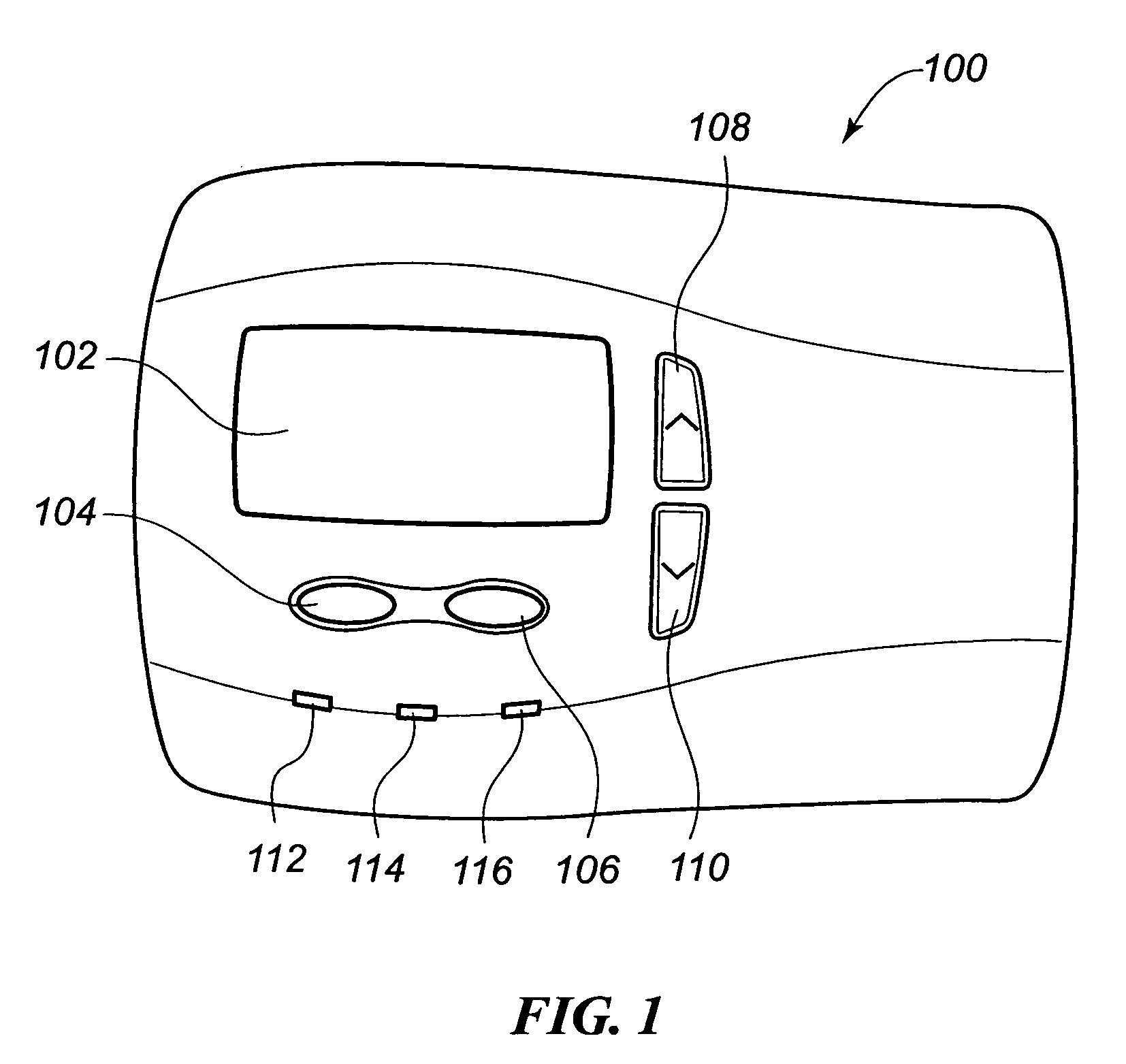
[0016] An embodiment of a thermostat constructed in accordance with the teachings of the present invention that incorporates the display system of the present invention is illustrated in FIG. 1. As with many thermostats, an internal temperature sensor is included within the thermostat 100. As may be seen from this FIG. 1, this embodiment of the thermostat 100 includes a user display 102 on which is displayed programmatic, system, and ambient information regarding the operation of the HVAC system. This user display 102 may take various forms as are well-known in the art, and in a preferred embodiment is a dot matrix LCD display. With such a display 102, the consumer may activate various programmatic and control functions via a pair of soft keys 104, 106. The functionality executed by these soft keys 104, 106 varies dependent upon the programmatic state in which the thermostat 100 is at the time one of the soft keys 104, 106 is depressed. The particular functionality that will be inst...


PUM


Abstract

A visual display system for use with a digital thermostat is provided. The visual display system provides an adjustable display resolution for the temperature readout provided thereon. This adjustable display resolution may be changed as desired by a user via a resolution adjustment menu. The display resolution may be adjusted to display the temperature information in tenths of degrees, half degrees, whole degrees, etc. as desired by a user. Such a display system accommodates different display resolution requirements of different original equipment manufacturer (OEM) customers who may desire different displayed resolutions without having to manufacture and stock different models.

Description

FIELD OF THE INVENTION [0001] The present invention relates generally to digital thermostats, and more particularly to digital thermostats that have a user interface display screen for displaying of heating, ventilating and air conditioning (HVAC) information. BACKGROUND OF THE INVENTION [0002] Occupants of dwellings and commercial structures have long benefited from the inclusion of a heating, ventilating, and air conditioning (HVAC) system that regulates the temperature and humidity within the dwelling or structure. Traditionally, the thermostat that controlled this temperature regulating equipment was a fairly simple electromechanical device that would allow a user to rotate a dial to a desired set point. While the resolution of the temperature information on the dial varied from model to model, it is typically not better than two degrees, and is only indicated by a moving pointer on the dial. [0003] Advances in control electronics have allowed the development of new, digital the...

Claims


Application Information

Patent Timeline
IPC IPC(8): G05D23/00
CPCF24F2011/0091F23N5/203F24F11/52G05D23/00G06F3/048
Inventor CHAPMAN, JOHN GILMAN JR.GRAY, TONY
Owner RANCO OF DELAWARE
Learn More