Vehicle brake system

a brake system and vehicle technology, applied in the field of vehicle brake systems, can solve the problems of reducing frictional braking force, reducing regenerative braking force to zero, and taking a rather long time to reduce frictional braking force, so as to quickly eliminate any wheel locking tendency, reliably recover energy by regenerative braking, and quick reducing braking force

Inactive Publication Date: 2007-03-01
ADVICS CO LTD
View PDF2 Cites 57 Cited by
  • Summary
  • Abstract
  • Description
  • Claims
  • Application Information

AI Technical Summary

Benefits of technology

[0008] In this arrangement, the braking force ratio adjuster keeps the regenerative braking force to the predetermined force before the start of the anti-lock control, and the regenerative braking force reducer reduces the regenerative braking force from the predetermined force when the anti-lock control starts. Thus, upon the start of the anti-lock control, it is possible to quickly reduce the braking force and thus to quickly eliminate a locking tendency of any wheel. Also, it is possible to reliably recover energy by regenerative braking.
[0009] Preferably, the brake system further comprises a friction coefficient detector for detecting the friction coefficient of the road surface on which the vehicle is traveling, and the predetermined force is determined by the braking force ratio adjuster based on the friction coefficient detected by the friction coefficient detector. With this arrangement, because the value at which the regenerative braking force is kept before the start of the anti-lock control is determined based on the friction coefficient of the road surface, it is possible, at the start of the anti-lock control, to quickly eliminate a locking tendency of any wheel by reducing the regenerative braking force while suppressing the reduction of the regenerative braking force.
[0010] Preferably, the predetermined force is determined by the braking force ratio adjuster to half the maximum frictional force generated on the road surface of which the friction coefficient is detected by the friction coefficient detector. With this arrangement, it is possible, at the start of the anti-lock control, to quickly eliminate a locking tendency of any wheel by reducing the regenerative braking force while further suppressing the reduction of the regenerative braking force.
[0011] The braking force ratio adjuster preferably comprises a slip rate detector for detecting the slip rate of the wheel, a regenerative braking force adjuster for reducing the regenerative braking force corresponding to an increase in the slip rate to the predetermined force and keeping the regenerative braking force at the predetermined force, before the anti-lock control starts, and a frictional braking force adjuster for increasing the frictional braking force corresponding to a reduction in the regenerative braking force while the regenerative braking force is being reduced by the regenerative braking force adjuster. With this arrangement, even if the slip rate sharply increases before the anti-lock control, the regenerative braking force can be reduced quickly corresponding to the increase in the slip rate. This reliably prevents a sharp drop of the vehicle deceleration due to a reduction in the regenerative braking force at the start of the anti-lock control.
[0012] Preferably, the regenerative braking force adjuster of such a braking force ratio adjuster has an additional function of increasing the regenerative braking force corresponding to a reduction in the slip rate, and the frictional braking force adjuster of the braking force ratio adjuster has an additional function of reducing the frictional braking force corresponding to an increase in the regenerative braking force while the regenerative braking force is being increased by the regenerative braking adjuster. With this arrangement, when the slip rate decreases, the regenerative braking force increases corresponding to the reduction in the slip rate, so that energy can be recovered more efficiently by regenerative braking before the start of the anti-lock control.
[0013] According to the present invention, the regenerative braking force is maintained at a predetermined force before the start of the anti-lock control, and is reduced from the predetermined force at the start of the anti-lock control. The braking force thus decreases quickly at the start of the anti-lock quickly, so that it is possible to quickly eliminate a locking tendency of any wheel, thus stabilizing the vehicle.

Problems solved by technology

In this arrangement, there is the possibility that the regenerative braking force may decrease to zero before the start of the anti-lock control and as a result, only the frictional braking force is applied to the wheels.
Compared to electrically generated regenerative braking force, mechanically generated frictional braking force cannot be sufficient quickly increased or reduced in response to a control signal.
Thus, it takes a rather long time to reduce frictional braking force until the locking tendency of the wheel is eliminated.
This could destabilize the behavior of the vehicle.
Also, if the regenerative braking force drops to zero before the start of the anti-lock control, it becomes impossible to recover energy by regenerative braking, thus lowering energy efficiency of the vehicle.

Method used


Image

  • Vehicle brake system
  • Vehicle brake system
  • Vehicle brake system

Examples


Embodiment Construction

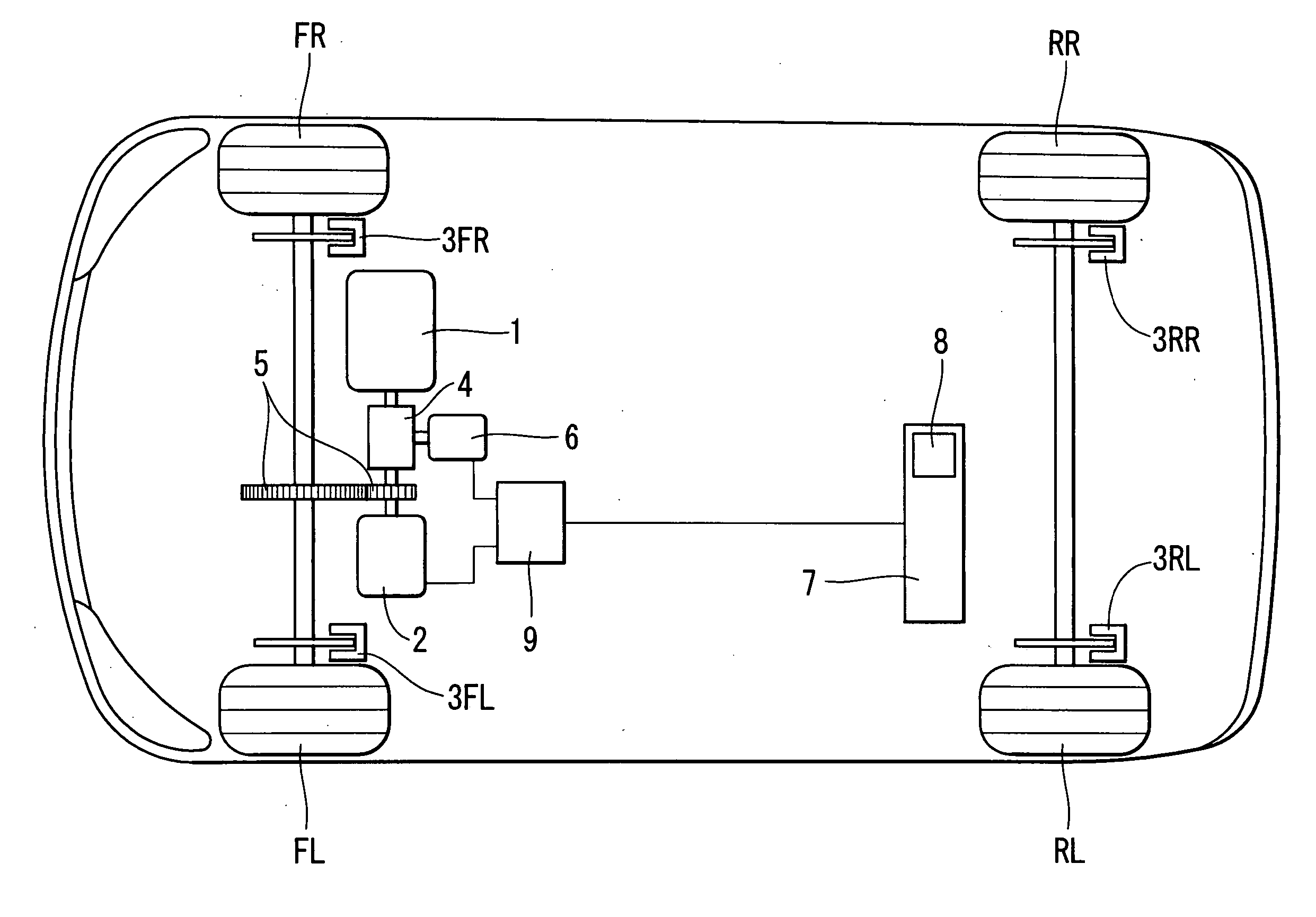
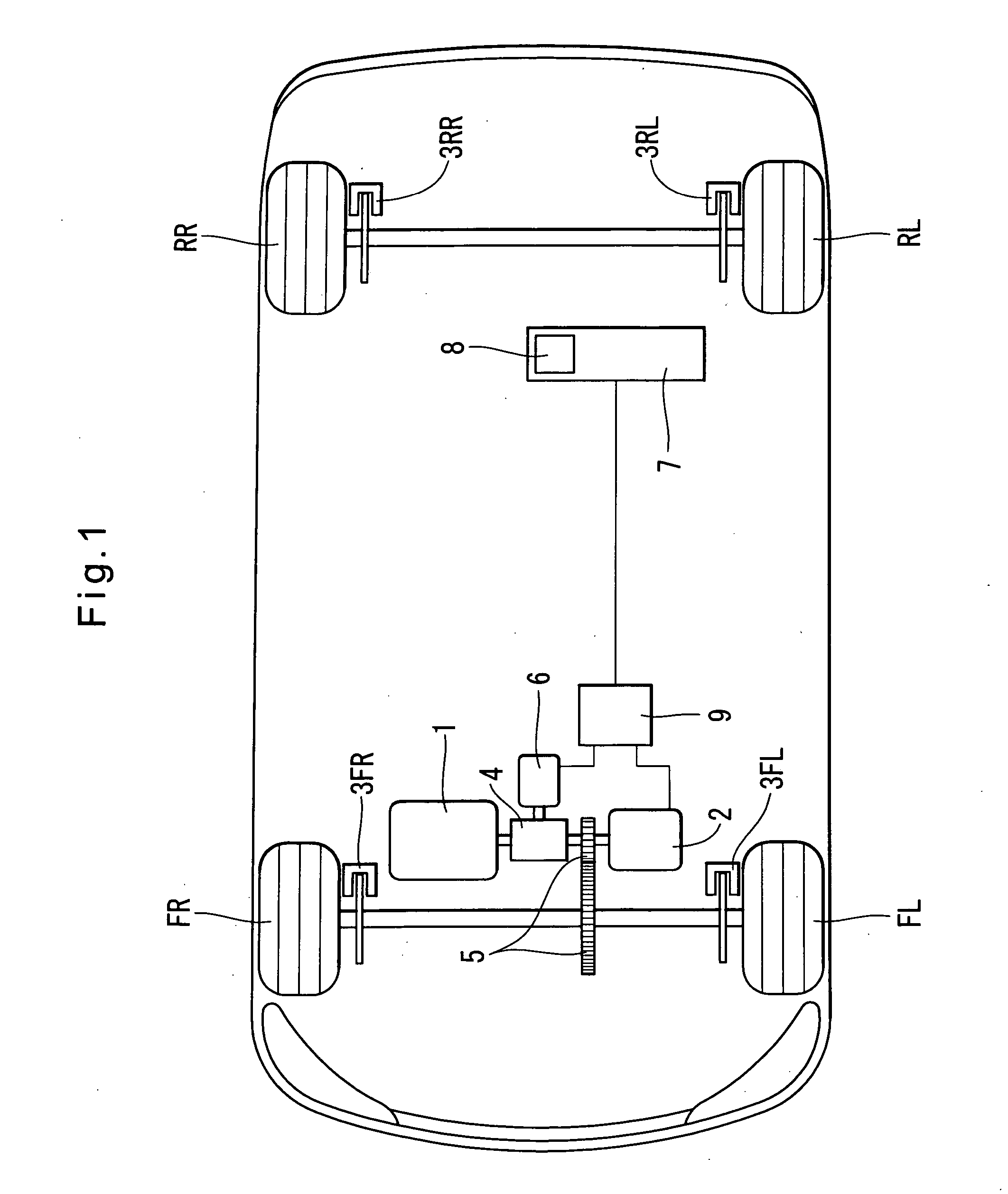
[0032]FIG. 1 schematically shows a vehicle including the brake system according to the present invention. The vehicle shown carries what is known as a hybrid drive system comprising an engine 1 and an electric motor 2. The brake system shown includes friction brake units 3FL, 3FR, 3RL and 3RR which are mounted to the front wheels FL and FR and the rear wheels RL and RR, respectively, to produce frictional braking force.

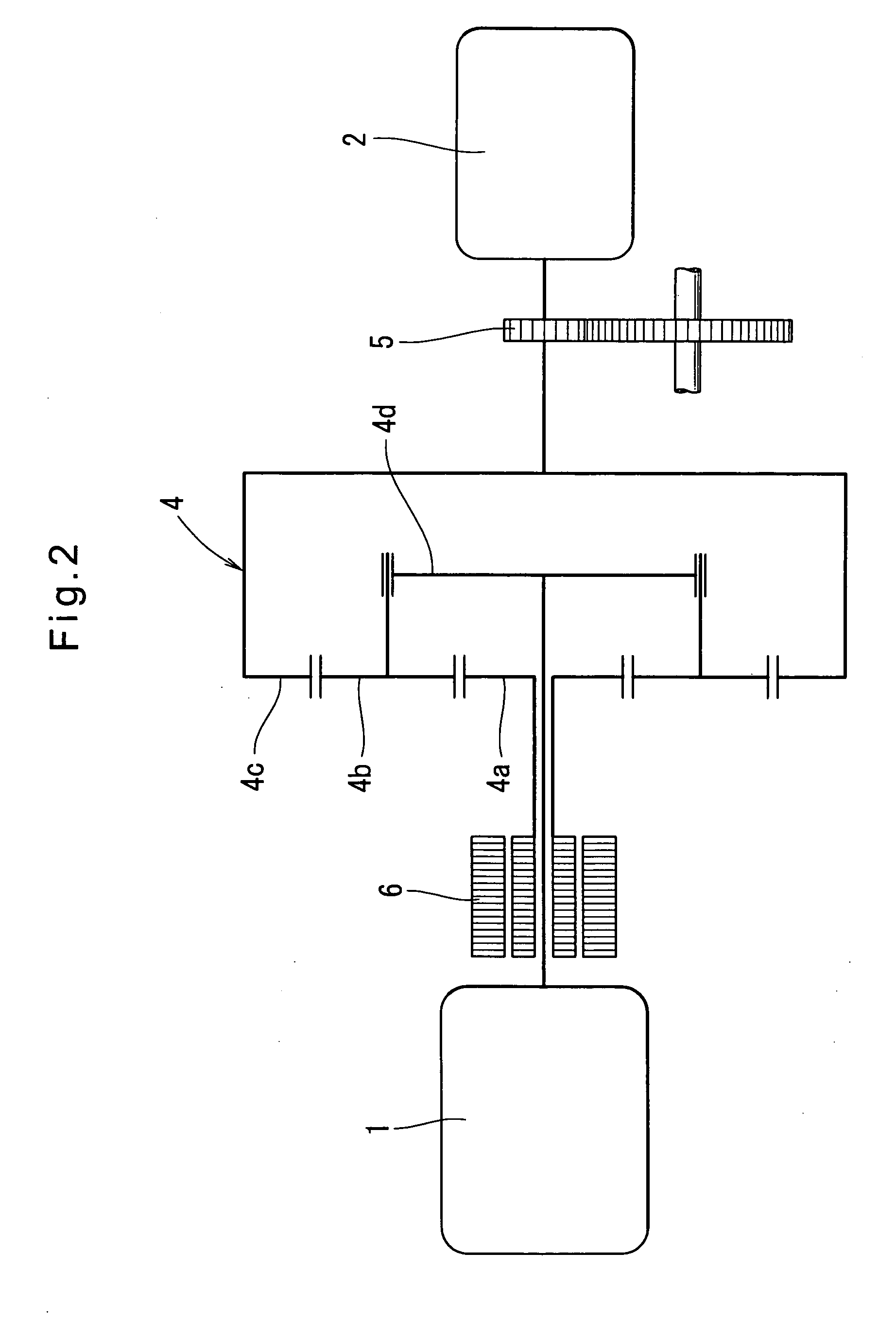
[0033] The engine 1 is connected to the front wheels FR and FL through a power split device 4 and reduction gears 5. As shown in FIG. 2, the power split device 4 comprises a sun gear 4a, planetary gears 4b that rotate about the sun gear 4a while meshing with the sun gear 4a, a ring gear 4c having internal gear teeth meshing with the planetary gears 4b, and a planet carrier 4d supporting the planetary gears 4b. The planetary carrier 4d is coupled to the engine 1, the ring gear 4c is coupled to the reduction gears 5, and the sun gear 4a is coupled to a generator 6. Thu...


PUM


Abstract

An improved vehicle brake system for controlling the frictional braking force and the regenerative braking force to be applied to a wheel of a vehicle. The brake system reduces the regenerative braking force to a predetermined force and keeps the regenerative braking force at the predetermined force before the start of anti-lock control. When the anti-lock control starts, the brake system decreases the regenerative braking force from the predetermined force. With this arrangement, it is possible to quickly eliminate a locking tendency of any wheel of the vehicle, thereby stabilizing the vehicle.

Description

CROSS REFERENCE TO RELATED APPLICATIONS [0001] This application is based on and claims priority under 35 U.S.C. sctn. 119 with respect to Japanese Patent Application No. 2005-248117 filed on Aug. 29, 2005, the entire content of which is incorporated herein by reference. BACKGROUND OF THE INVENTION [0002] The present invention relates to a vehicle brake system having an anti-lock control function for preventing lockup of the vehicle wheels while the brakes are being applied to the wheels. [0003] Among such known vehicle brake systems, there are ones comprising a friction mechanism for applying frictional braking force to vehicle wheels and a motor for applying regenerative braking force to vehicle wheels. The motor applies regenerative braking force to a plurality of wheels, typically to drive wheels, all at once. Thus, as soon as the anti-lock control, which is performed on individual wheels, starts, the regenerative braking function is disabled, and the anti-lock control is perform...

Claims


Application Information

Patent Timeline
Patent Type & Authority Applications(United States)
IPC IPC(8): B60T8/64B60T8/17B60T8/172B60T8/1761B60T8/1763B60W40/068
CPCB60K1/02B60K6/365B60K6/445B60T1/10B60T8/17616Y02T10/6239B60W10/08B60W10/184B60W20/00B60W30/18127B60T2270/602Y02T10/62B60W20/13
Inventor MATSUURA, MASAHIROKOKUBO, KOICHISAITO, SHIGERUSENGOKU, YUJI
Owner ADVICS CO LTD
Why Eureka
Try Eureka