PIFA, RFID tag using the same and antenna impedance adjusting method thereof

a technology of radio frequency identification and impedance adjustment, which is applied in the direction of antenna earthing, antenna structure form, resonance antenna, etc., can solve the problems of affecting the return loss characteristics and radiation pattern characteristics of the tag antenna, bit too large to be used as a radio frequency identification (rfid) tag antenna, and requiring a lot of attention in designing an antenna, etc., to achieve easy impedance matching

Inactive Publication Date: 2007-03-01
ELECTRONICS & TELECOMM RES INST
View PDF13 Cites 36 Cited by
  • Summary
  • Abstract
  • Description
  • Claims
  • Application Information

AI Technical Summary

Benefits of technology

[0009] It is, therefore, an object of the present invention to miniaturize an antenna by using a meander line extended from a radiating edge of a radiation patch during antenna designing and adjusting a resonant frequency of the antenna, and make it easy to perform impedance matching in the antenna by adjusting capacitive reactance of the antenna.

Problems solved by technology

In particular, when a tag antenna is attached to metal, the return loss characteristics and radiation pattern characteristics of the tag antenna can be affected seriously.
Therefore, designing an antenna requires much attention.
However, since it has a size of a half wavelength in a resonant frequency, it is a bit too large to be used as a Radio Frequency Identification (RFID) tag antenna.
However, since the PIFA suggested in the paper by Kashiwa et al. cannot adjust the antenna impedance at a feeding point, there is a problem that the location of the feeding point should be changed when the feeding point where the impedance becomes 50Ω according to a change in an environment, for example, when the size of the metallic object is changed.
Also, since the PIFA suggested in the paper by Kashiwa et al. has a size of a fourth wavelength in the resonant frequency, there is another problem that the size of the antenna is a bit large.
Moreover, the PIFA suggested in the paper by Kashiwa et al. cannot support the RFID service sufficiently.
The PIFA suggested in the U.S. Pat. No. 6,741,214, however, can hardly control inductive reactance and capacitive reactance in diverse levels with the impedance controlling stub.
Also, the PIFA of the cited patent has a limitation in miniaturization and it has a problem that the dielectric substance which is used for mechanical stability reduces the bandwidth and radiation efficiency of the antenna.

Method used


Image

  • PIFA, RFID tag using the same and antenna impedance adjusting method thereof
  • PIFA, RFID tag using the same and antenna impedance adjusting method thereof
  • PIFA, RFID tag using the same and antenna impedance adjusting method thereof

Examples


Embodiment Construction

[0025] Other objects and aspects of the invention will become apparent from the following description of the embodiments with reference to the accompanying drawings, which is set forth hereinafter.

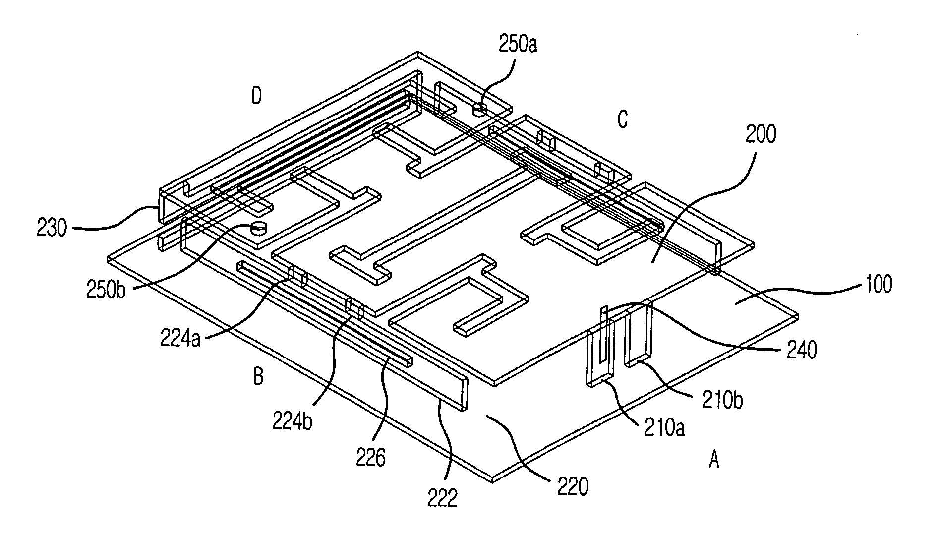
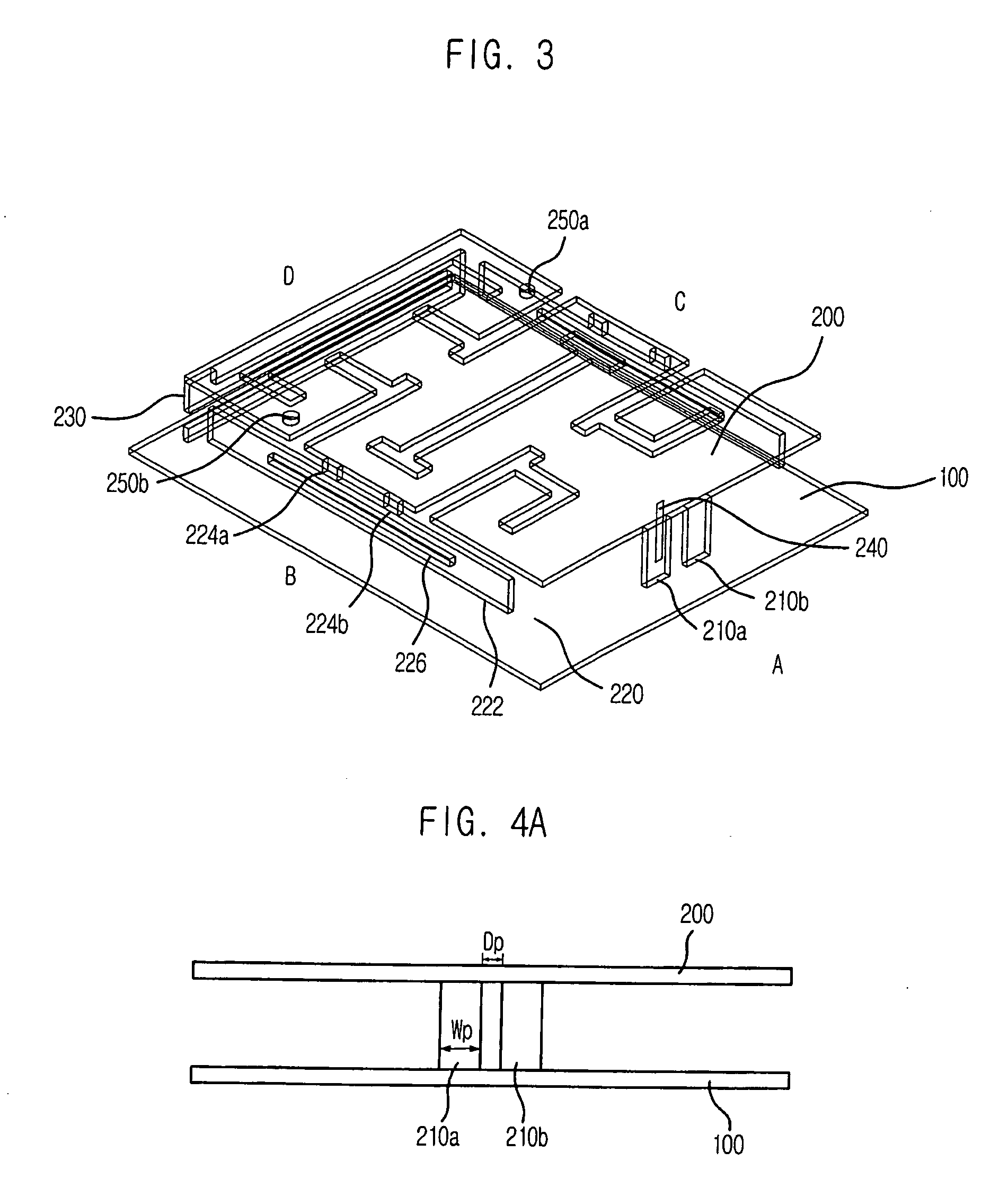
[0026]FIG. 3 is a perspective view describing a Planar Inverted-F Antenna (PIFA) in accordance with an embodiment of the present invention. The PIFA includes a ground surface 100 in the lower part and a radiation patch 200 with a predetermined space from the ground surface 100. The radiation patch 200 is short from the ground surface 100 by shorting plates 210a and 210b. The radiation patch 200 has a radiating edge where radiation occurs mainly and a non-radiating edge. In FIG. 3, the regions A, B and C of the shorting plates 210a and 210b correspond to the non-radiating edge, whereas the region D in opposite to the shorting plates 210a and 210b corresponds to the radiating edge.

[0027] In the non-radiating edges B and C of the antenna, reactance controlling stubs 250 are extended from th...


PUM


Abstract

Provided are a Planar Inverted-F Antenna (PIFA), a Radio Frequency Identification (RFID) tag using the PIFA. The present invention miniaturizes the antenna by using a meander line extended from a radiating edge of a radiation antenna and adjusting a resonant frequency of the antenna, and it performs impedance matching by adjusting capacitive reactance of the antenna. Also, it can perform impedance matching by using a stub having a slot formed therein and adjusting inductive reactance and capacitive reactance of the antenna. The present invention miniaturizes the antenna by using a plurality of shorting plates for shorting the radiation patch from a grounding surface and adjusting the resonant frequency of the antenna. The present invention also provides an inexpensive PIFA antenna with an excellent radiation efficiency by forming the radiation patch in the form of metal sheet in the antenna and floating the radiation patch in the air.

Description

FIELD OF THE INVENTION [0001] The present invention relates to a Planar Inverted-F Antenna (PIFA), a Radio Frequency Identification (RFID) tag using the PIFA, and an antenna impedance adjusting method thereof; and, more particularly, to a PIFA having a meander line and a reactance controlling stub, an RFID tag using the PIFA, and an antenna impedance adjusting method thereof. DESCRIPTION OF RELATED ART [0002] Differently from an active RFID reader, a tag is attached to an object of diverse materials and shapes. Minimizing the degradation of antenna characteristics due to the material used for the attachment is the conceptional purpose of tag antenna design. In particular, when a tag antenna is attached to metal, the return loss characteristics and radiation pattern characteristics of the tag antenna can be affected seriously. Therefore, designing an antenna requires much attention. When an ordinary dipole antenna is brought close to a metallic object, the radiation of electromagneti...

Claims


Application Information

Patent Timeline
Patent Type & Authority Applications(United States)
IPC IPC(8): H01Q1/38
CPCH01Q1/22H01Q9/0442H01Q9/0421
Inventor CHOI, WON-KYUSEONG, NAK-SEONPYO, CHEOL-SIGCHAE, JONG-SUK
Owner ELECTRONICS & TELECOMM RES INST
Why Eureka
Try Eureka