Flat profile tape head

a tape head and flat profile technology, applied in the field of magnetic head structures, can solve the problems of tape not moving across the tape bearing surface perfectly linearly, dynamic skew, and misalignment of trailing readers with leading writers, and achieve the effect of reducing wear on the third modul

Inactive Publication Date: 2007-03-01
IBM CORP
View PDF19 Cites 55 Cited by
  • Summary
  • Abstract
  • Description
  • Claims
  • Application Information

AI Technical Summary

Benefits of technology

[0016] In an embodiment, a tape passing across the first module prior to passing across the third module does not become parallel to the tape bearing surface of the third module w

Problems solved by technology

However, the tape does not move across the tape bearing surfaces perfectly linearly.
Rather, the tape may shift back and forth, or “wobble,” as it crosses the tape bearing surfaces, resulting in dynamic skew, or misalignment of the trailing readers with the leading writers.
The farther the readers are behind the writers, the mor

Method used


Image

  • Flat profile tape head
  • Flat profile tape head
  • Flat profile tape head

Examples


embodiment 400

[0051] The outer wrap angles can also be set by outriggers. FIG. 4 illustrates an embodiment 400 where outriggers 402 are formed on the outer modules 302, 306.

[0052] The outriggers 402 control the outer wrap angle α1 of the tape 315 relative to the tape bearing surfaces 308 of the leading module 302. As shown, each outrigger 402 may have a flat tape bearing surface 404 that, like typical flat profile heads, induces a small spacing between a tape 315 passing thereover and its tape bearing surface 404. The outrigger 402 may lie on a parallel plane as the tape bearing surface of the associated module. In such an embodiment, the outrigger tape bearing surface 404 is positioned below the plane of the tape bearing surface of the associated element, thereby creating the proper wrap angle α1 of the tape 315 relative to the tape bearing surface of the associated module.

[0053] A benefit of this embodiment is that, because the outrigger 402 may be formed directly on the module, the outer wrap...

embodiment 500

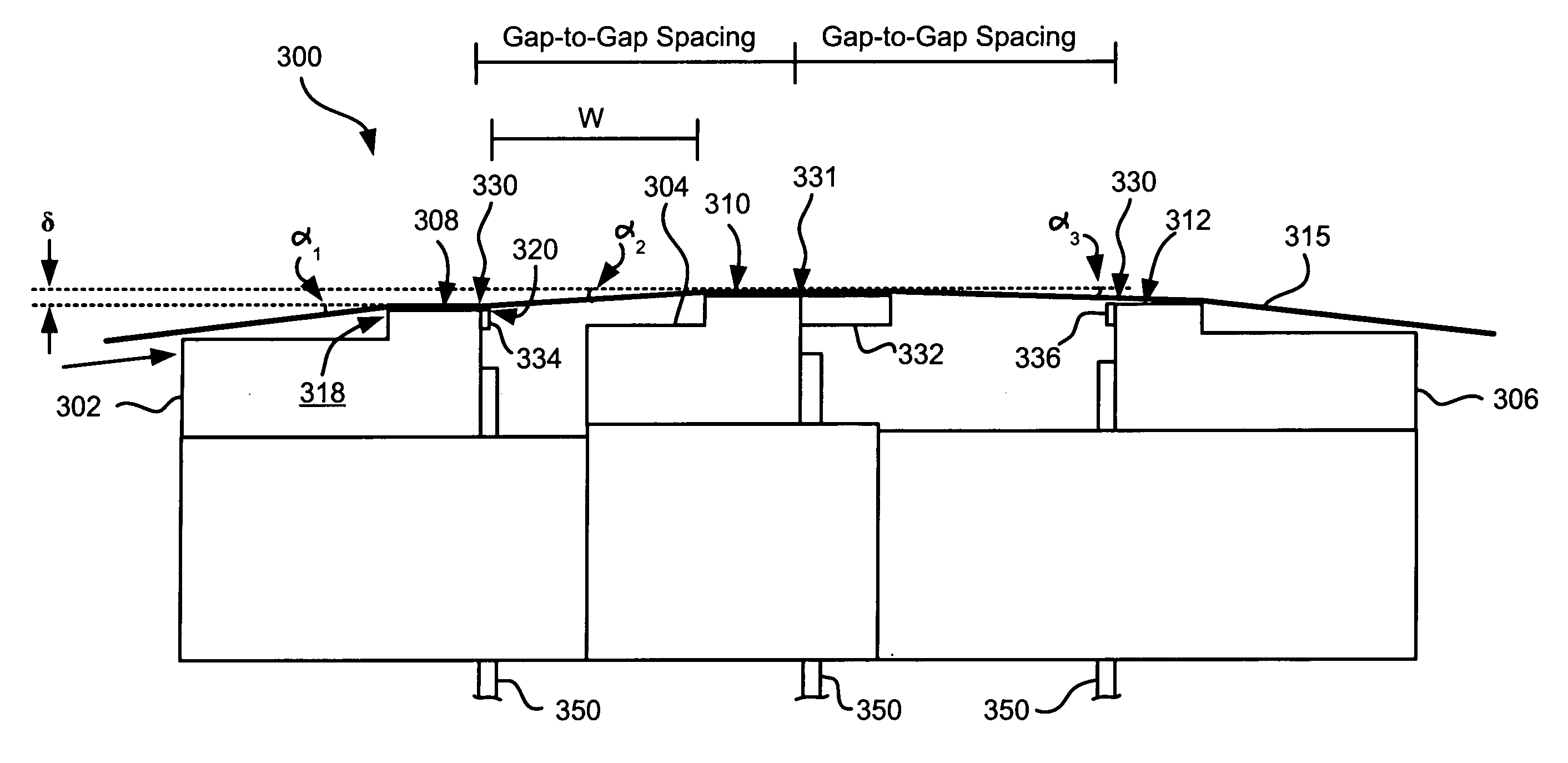
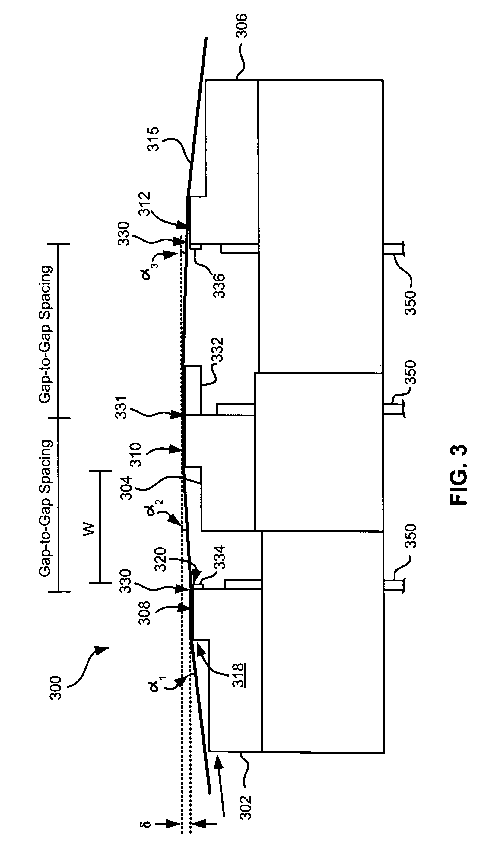
[0056] Depending on tape tension and stiffness, it may be desirable to angle the tape bearing surfaces of the outer modules relative to the tape bearing surface of the second module. FIG. 5 illustrates an embodiment 500 where the modules 302, 304, 306 are in a tangent (angled) configuration. Particularly, the tape bearing surfaces of the outer modules 302, 306 are about parallel to the tape at the desired wrap angle α2 of the second module 304. In other words, the planes of the tape bearing surfaces 308, 312 of the outer modules 302, 306 are oriented at about the desired wrap angle α2 of the tape 315 relative to the second module 304. The inventor has found that the tape will also pop off of the trailing module 306 in this embodiment, thereby reducing wear on the elements in the trailing module 306. These embodiments are particularly adapted for write-read-write applications. Additional aspects of these embodiments are similar to those given above.

embodiment 600

[0057]FIG. 6 illustrates an embodiment 600 where the modules 302, 304, 306 are in an overwrap configuration. Particularly, the tape bearing surfaces 308, 312 of the outer modules 302, 306 are angled slightly more than the tape 315 when set at the desired wrap angle α2 relative to the second module 304. In this embodiment, the tape does not pop off of the trailing module, allowing it to be used for writing or reading. Accordingly, the leading and middle modules can both perform reading and / or writing functions while the trailing module can read any just-written data. Thus, these embodiments are preferred for write-read-write, read-write-read, and write-write-read applications. In the latter embodiments, closures should be wider than the tape canopies for ensuring read capability. The wider closures will force a wider gap-to-gap separation. Therefore the preferred embodiment has a write-read-write configuration, which may use shortened closures that thus allow closer gap-to-gap separa...


PUM


Abstract

A magnetic head according to one embodiment includes a first module having a flat profile tape bearing surface, a second module having a flat profile tape bearing surface, and a third module having a flat profile tape bearing surface. The third module is positioned on an opposite side of the second module than the first module. The tape bearing surfaces of the first, second and third modules may lie along substantially parallel planes, may be configured in a tangent (angled) configuration, or may be configured in an overwrap configuration. Data writing and reading functions are usually performed by different modules at a given time.

Description

RELATED APPLICATIONS [0001] This application is related to U.S. patent application entitled “MULTI-FORMAT MAGNETIC HEAD” to Biskeborn et al., filed concurrently herewith, and U.S. patent application entitled“MAGNETIC HEAD WITH PLANAR OUTRIGGER” to Biskeborn et al., filed concurrently herewith.FIELD OF THE INVENTION [0002] The present invention relates to magnetic head structures, and more particularly, this invention relates to a magnetic head structure having multiple modules and modes of operation. BACKGROUND OF THE INVENTION [0003] Business, science and entertainment applications depend upon computers to process and record data, often with large volumes of the data being stored or transferred to nonvolatile storage media, such as magnetic discs, magnetic tape cartridges, optical disk cartridges, floppy diskettes, or floptical diskettes. Typically, magnetic tape is the most economical and convenient means of storing or archiving the data. Storage technology is continually pushed t...

Claims


Application Information

Patent Timeline
IPC IPC(8): G11B5/10
CPCG11B5/00826G11B5/10G11B5/40G11B5/23G11B5/255G11B5/1871
Inventor BISKEBORN, ROBERT GLENN
Owner IBM CORP
Why Eureka
Try Eureka