
Shaft for constant velocity universal joint

Inactive Publication Date: 2007-03-01
NTN CORP
View PDF8 Cites 7 Cited by
  • Summary
  • Abstract
  • Description
  • Claims
  • Application Information

AI Technical Summary

Benefits of technology

[0014] The present invention has been conceived in view of the foregoing situation, with an object to provide a shaft for a constant velocity universal joint capable of suppressing a rotational backlash when incorporated in the constant velocity universal joint, and improving the assembly efficiency as well as reducing the manufacturing cost.

Problems solved by technology

Increasing the interference, however, leads to degraded assembly work efficiency because an enormous pressing load is required for fitting the members.
That is where the difficulty lies in controlling the mutual interference of the torque transmission unit to be within an appropriate range.
On the other hand, when the inner member 110 or the like and the yoke 50 are fixed by welding, although the rotational backlash does not emerge between the members, the welded portion is exposed to high temperature, which incurs distortion that leads to degradation in precision or a crack inside the joint, thereby lowering the yield of the joint 101.
In addition, when the inner member 110 and the yoke 50 are fixed by bonding, the secular deterioration of the adhesive may incur an increase in a gap in a rotation direction between the members of the torque transmission unit, thus provoking the rotational backlash.

Method used


Image

  • Shaft for constant velocity universal joint
  • Shaft for constant velocity universal joint
  • Shaft for constant velocity universal joint

Examples


Embodiment Construction

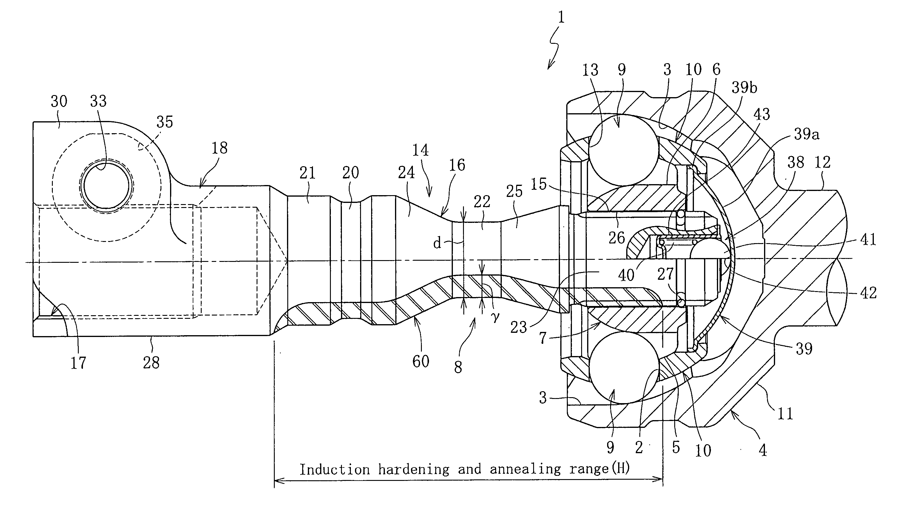
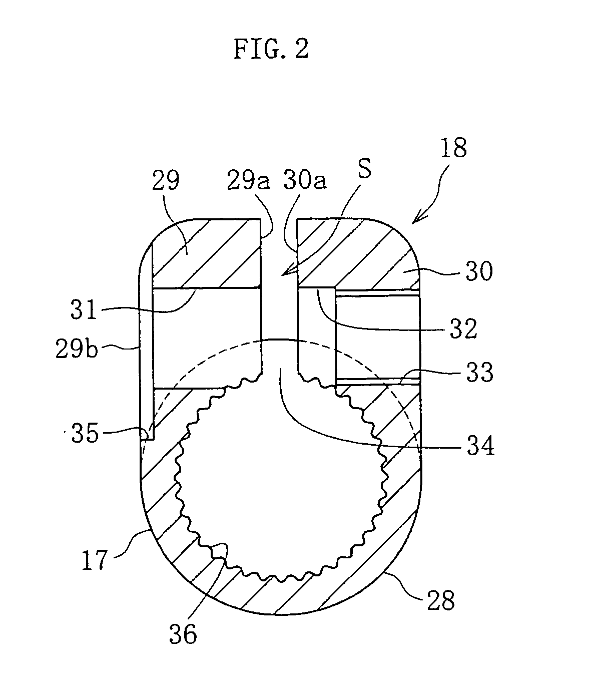
[0031] Referring to FIGS. 1 through 4, embodiments of the present invention will be described hereunder.

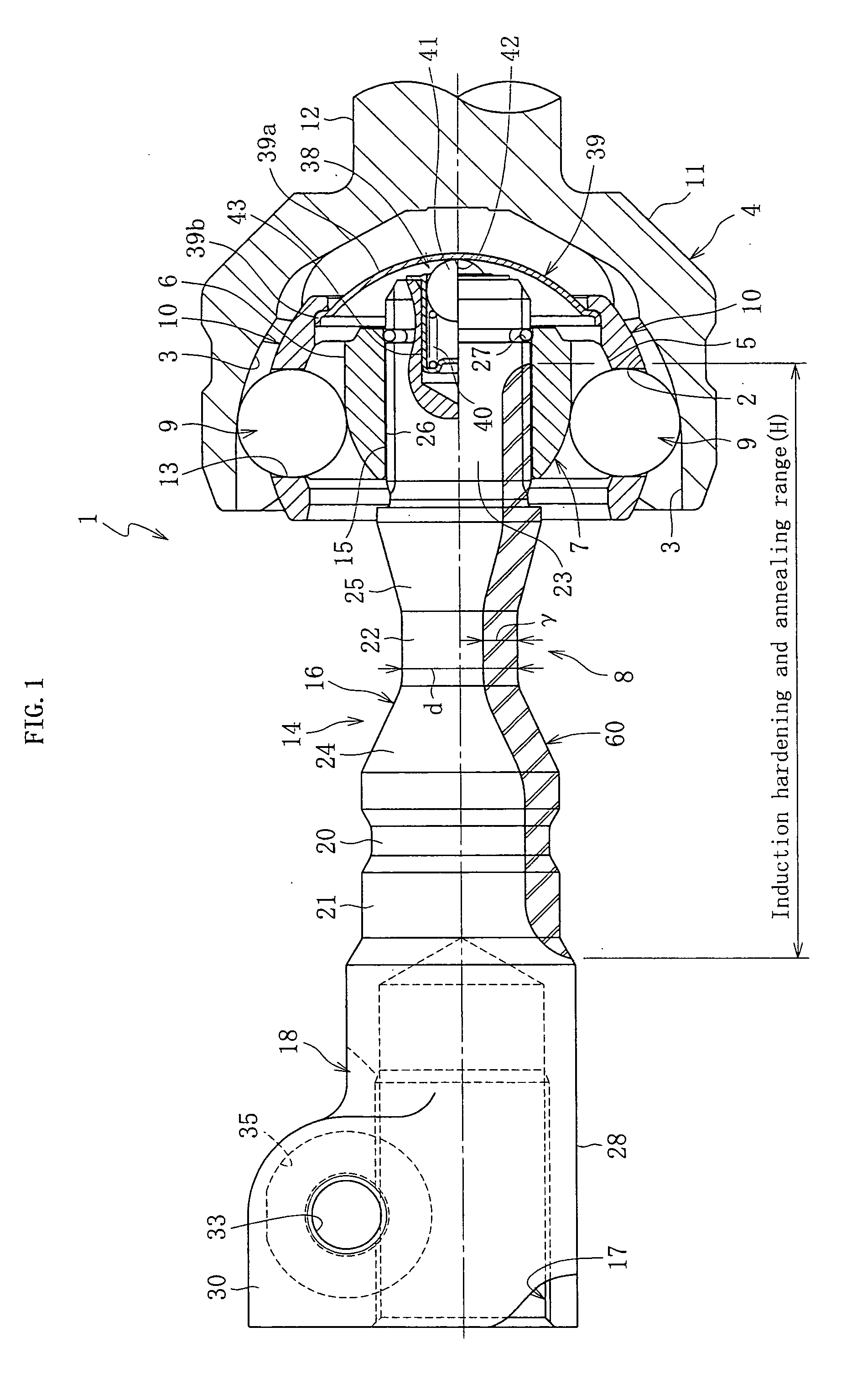
[0032]FIG. 1 depicts an entirety of a constant velocity universal joint shaft according to a first embodiment of the present invention. A constant velocity universal joint 1 used with the constant velocity universal joint shaft 14 includes an outer member 4 with a plurality of raceways 3 formed on an inner diametral surface (spherical inner surface) 2, an inner member 8 including an inner race 7 with a plurality of raceways 6 formed on an outer diametral surface (spherical outer surface) 5, a ball 9 located on each of a plurality of ball tracks formed by collaboration of the raceway 3 of the outer member 4 and the raceway 6 of the inner member 8, and a retainer 10 including a plurality of ball pockets 13 that retain the ball 9 circumferentially aligned at a predetermined interval.

[0033] The outer member 4 includes a cup-shaped outer race 11 with the raceway 3, and a shaft 12 pro...


PUM


Abstract

A constant velocity universal joint shaft, capable of suppressing a rotational backlash when incorporated in the constant velocity universal joint, and improving the assembly efficiency as well as reducing the manufacturing cost, is to be provided. The present invention relates to the constant velocity universal joint shaft having a spline that fits an inner race of the constant velocity universal joint. The shaft includes a shaft body with a spline formed thereon, and a yoke portion with a ring-shaped fitting portion. The shaft body and the yoke portion are integrally formed of medium carbon steel. By a pressing force of a pressing member the fitting portion of the yoke portion is tightened, so that such fitting portion fits a shaft external to the joint. In the constant velocity universal joint, the pressing member and an abutment member are elastically butted via an elastic member, so that a ball constantly remains in contact with a raceway of an outer member and a raceway of an inner member.

Description

TECHNICAL FIELD [0001] The present invention relates to a shaft for a constant velocity universal joint, and more particularly to a shaft for a constant velocity universal joint incorporated in a steering apparatus of a vehicle. BACKGROUND OF THE INVENTION [0002] Constant velocity universal joints are broadly classified into a fixed type that only permits an angular displacement between an input shaft and an output shaft, and a sliding type that permits both an angular displacement and an axial displacement. The model of the constant velocity universal joint is selected according to the purpose and conditions of use of the respective cases. [0003]FIG. 5 shows an example of a fixed type constant velocity universal joint (hereinafter, simply “joint 101”). Based on the joint 101 as an example, a conventional constant velocity universal joint will be described. The joint 101 mainly includes an outer member 106 with a plurality of raceways 105 formed on a spherical inner surface (inner d...

Claims


Application Information

Patent Timeline
IPC IPC(8): F16D3/00F16D3/223F16D3/2237
CPCF16D2250/00F16D3/2237Y10S464/906
Inventor ISHIJIMA, MINORUYAMAZAKI, KENTA
Owner NTN CORP
Learn More