
Clothes drying machine

Inactive Publication Date: 2006-06-01
SAMSUNG ELECTRONICS CO LTD
View PDF3 Cites 6 Cited by
  • Summary
  • Abstract
  • Description
  • Claims
  • Application Information

AI Technical Summary

Benefits of technology

[0011] Therefore, one aspect of the invention is to provide a clothes drying machine having a simple connection structure of an air blowing case and a motor bracket, thereby reducing the number of components and improving assembly efficiency.
[0012] Another aspect of the invention is to provide a clothes drying machine, in which an air blowing case and a motor bracket are precisely assembled, thereby preventing the generation of noise or vibration.

Problems solved by technology

Since the air blowing case and the motor bracket are fixed to each other by the fixing screws, the clothes drying machine is disadvantageous in that there are many required components of the clothes drying machine and the assembly efficiency of the clothes drying machine is lowered due to steps of connecting the fixing screws during a manufacturing process.
When connection forces of the fixing screws are different due to carelessness of a worker or the clothes drying machine is not precisely assembled, the above connection structure of the air blowing case causes the vibration of the air blowing case, thus generating noise.

Method used


Image

  • Clothes drying machine
  • Clothes drying machine
  • Clothes drying machine

Examples


Embodiment Construction

[0026] Reference will now be made in detail to an illustrative, non-limiting embodiment of the present invention, an example of which is illustrated in the accompanying drawings, wherein like reference numerals refer to like elements throughout. The exemplary embodiment is described below to explain the present invention by referring to the accompanying drawings.

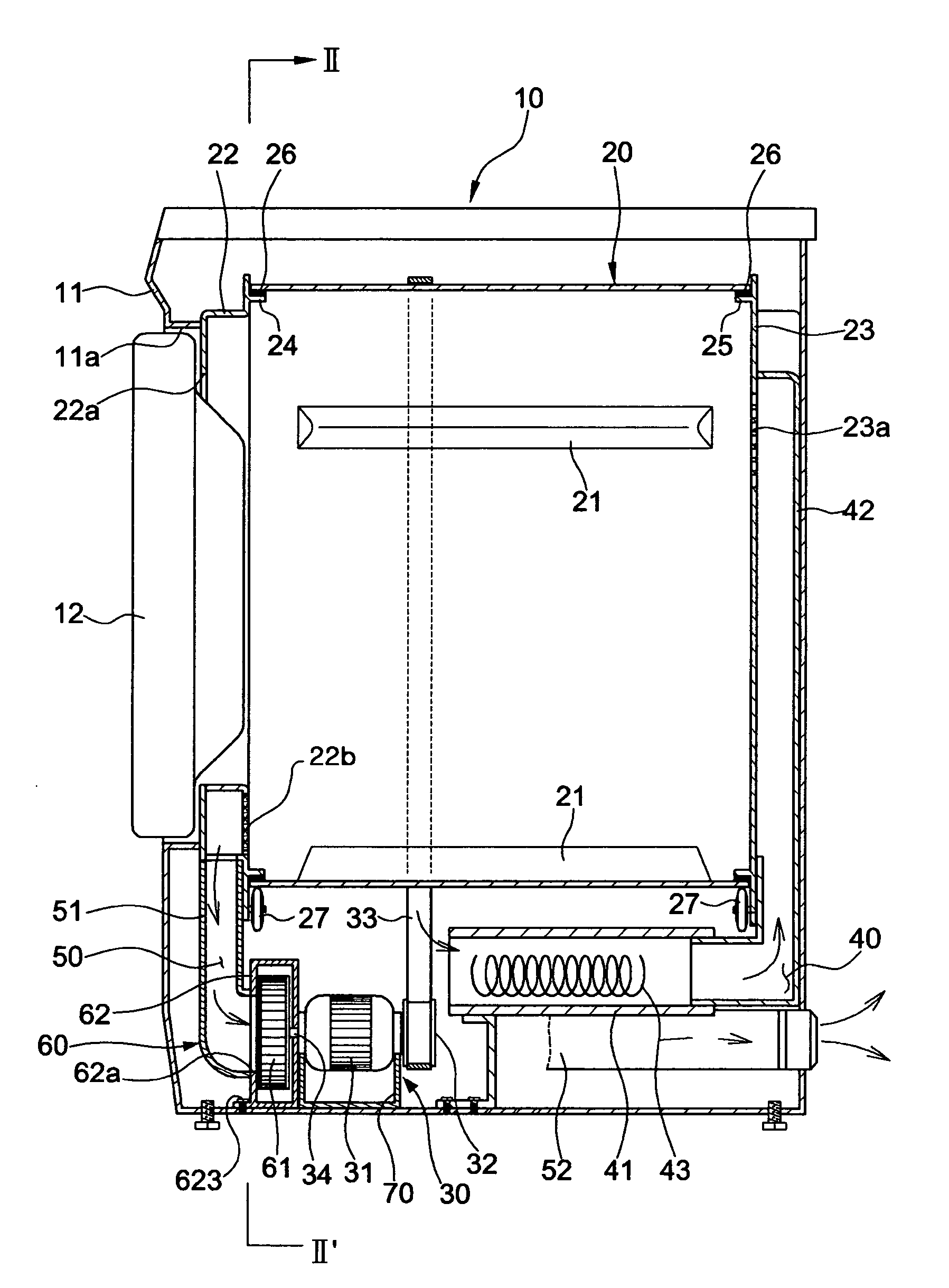
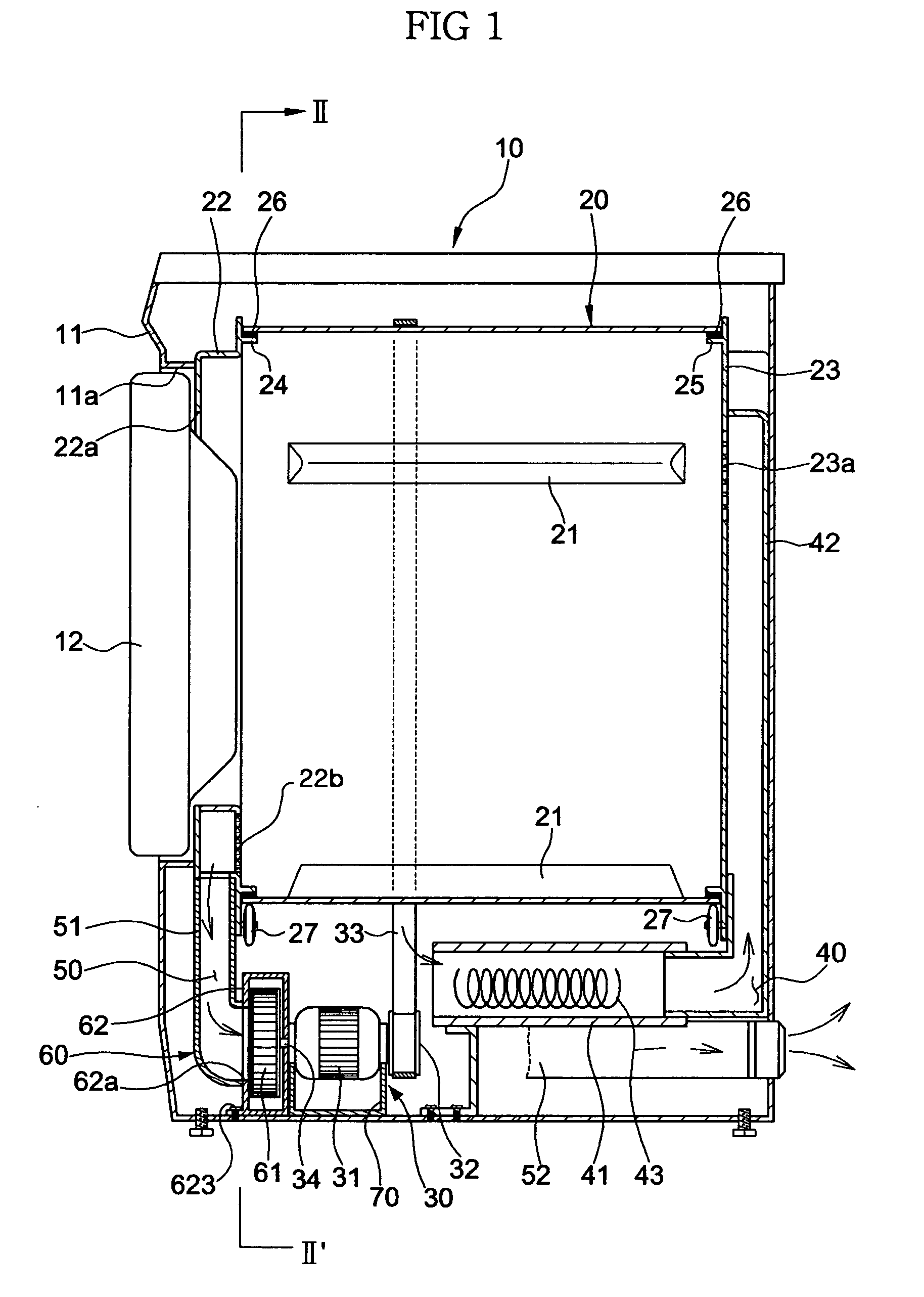
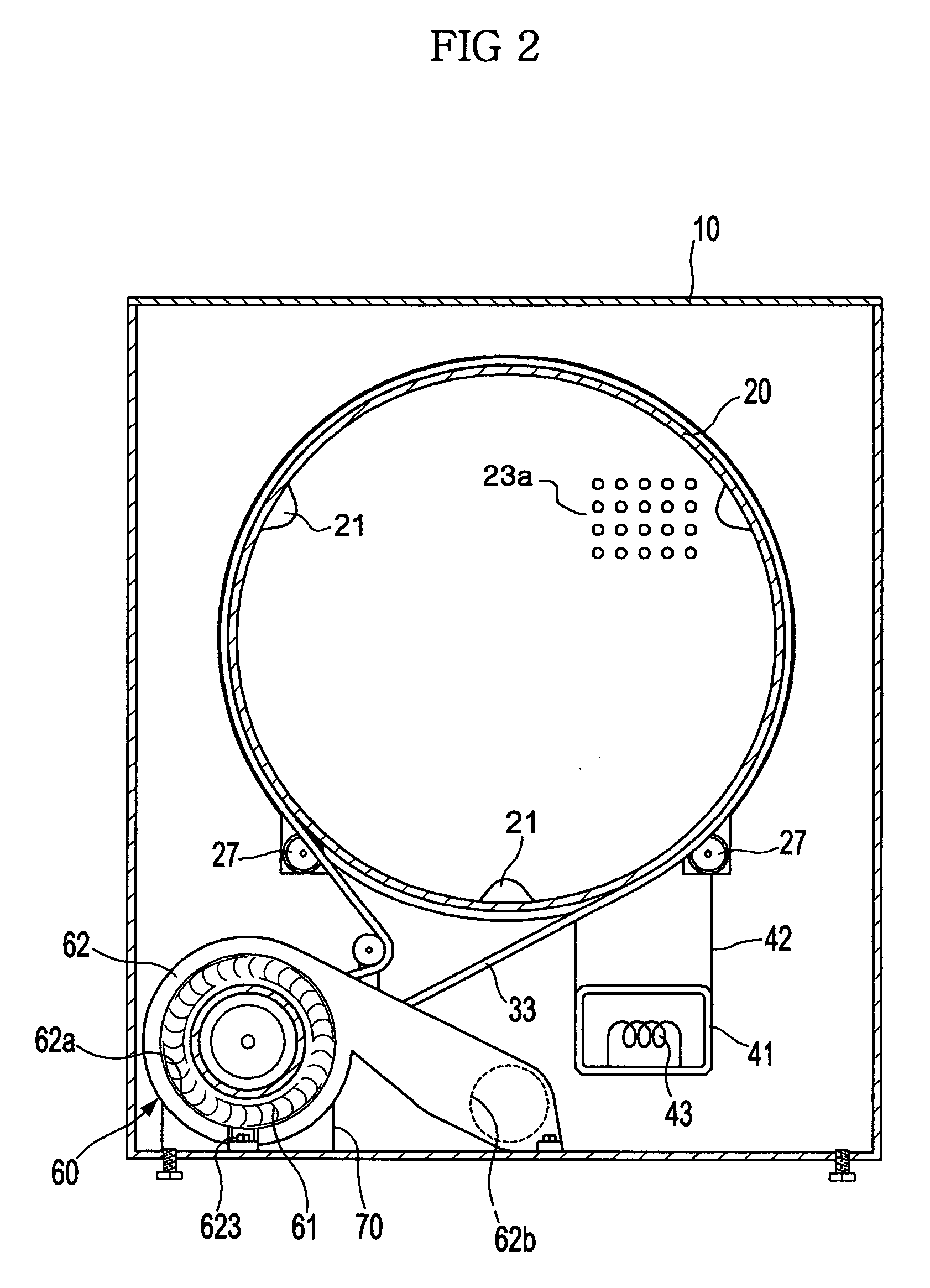
[0027] As shown in FIG. 1, the clothes drying machine of the present invention comprises a rotary drum 20 rotatably installed in an external case 10, a driving device 30 for rotating the rotary drum 20, a suction channel 40 and a discharge channel 50 for circulating air to the inside of the rotary drum 20, and an air blowing device 60.

[0028] The rotary drum 20 has a cylindrical structure, front and rear surfaces of which are opened, and includes a plurality of lifters 21 protruded in a mountain shape from the inner surface thereof for lifting laundry and then dropping the laundry. A front support plate 22 and a rear suppor...


PUM


Abstract

A clothes drying machine, in which a connection structure between an air blowing case and a motor bracket is simplified so that the number of required components is reduced and assembly efficiency is improved, and the air blowing case is precisely connected to the motor bracket so that the generation of noise or vibration is reduced. The clothes drying machine has an air blowing device including an air blast fan and an air blowing case; a driving motor installed proximate to the air blowing case for driving the air blast fan; a motor bracket for fixing the driving motor; a support portion extended from the motor bracket for fixing the air blowing case and determining the position of the air blowing case; first insertion portions, formed on an outer surface of the air blowing case, into which the end of the support portion is inserted; and a second insertion portion protruded from the outer surface of the air blowing case at a position separated from the first insertion portions for fixing the air blowing case.

Description

CROSS-REFERENCE TO RELATED APPLICATION [0001] This application claims priority from Korean Patent Application No. 2004-99925, filed Dec. 1, 2004, in the Korean Intellectual Property Office, the disclosure of which is incorporated herein by reference. BACKGROUND OF THE INVENTION [0002] 1. Field of the Invention [0003] The present invention relates to a clothes drying machine and, more particularly, to a clothes drying machine having an improved connection structure between a case of an air blowing device and a motor bracket. [0004] 2. Description of the Related Art [0005] A general drum-type clothes drying machine allows hot air to pass through the inside of a rotary drum under the condition that the rotary drum containing laundry is rotated at a low speed, thereby drying the laundry in the rotary drum. Korean Patent Laid-open Publication Nos. 2002-0062448 and 2004-0065477 disclose this type of clothes drying machine. [0006] The above clothes drying machine comprises an air blowing d...

Claims


Application Information

Patent Timeline
IPC IPC(8): F26B11/02
CPCD06F58/08D06F58/04D06F58/20
Inventor KIM, JIN DOO
Owner SAMSUNG ELECTRONICS CO LTD
Learn More