In-situ seal integrity monitoring

a seal integrity and monitoring technology, applied in fluid-tightness measurement, instruments, electrochemical generators, etc., can solve the problems of severe thermal stress, inconvenient monitoring of seal integrity, and consequent seal failur

Inactive Publication Date: 2007-03-08
ENRG +1
View PDF8 Cites 8 Cited by
  • Summary
  • Abstract
  • Description
  • Claims
  • Application Information

AI Technical Summary

Benefits of technology

[0007] The foregoing is achieved and an advance in the art is provided in a high-temperature seal having in-situ integrity monitoring capability, and a related seal monitoring method. The seal includes a quantity of dielectric material sealing an interface between adjacent structures and an electrical transmission line embedded within the dielectric material. A signal injection port is provided for exciting the transmission line with an excitation signal. A pair of sample ports (one of which can also be the signal injection port) are provided for sampling the transmission line to obtain signal samples...

Problems solved by technology

Failure to do so can lead to the development of severe thermal stresses and consequent seal failure during various device operational modes.
Unfortunately, it is very difficult to monitor seal integrity once a high-temperature device has been fabricated.
Is likewise very difficult to...

Method used


Image

  • In-situ seal integrity monitoring
  • In-situ seal integrity monitoring
  • In-situ seal integrity monitoring

Examples


Embodiment Construction

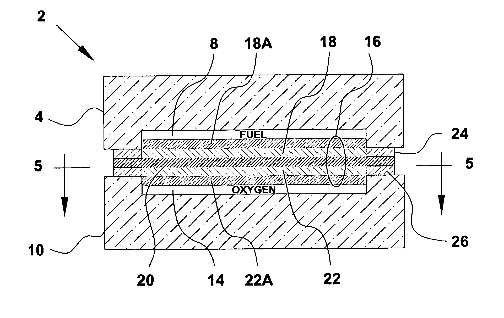
[0034] As summarized above, the present invention facilitates monitoring of the integrity of high-temperature seals constructed from dielectric materials, including glass, ceramic, plastic, etc. By embedding a transmission line within the seal and utilizing transmission line measurement techniques such as time domain reflectometry and / or frequency response analysis, anomalies such as seal dielectric constant variations and / or transmission line disruptions can be detected. Such evaluation provides useful information for making determinations about seal integrity in a manner that permits safe seal operation and minimization of resultant stress modes.

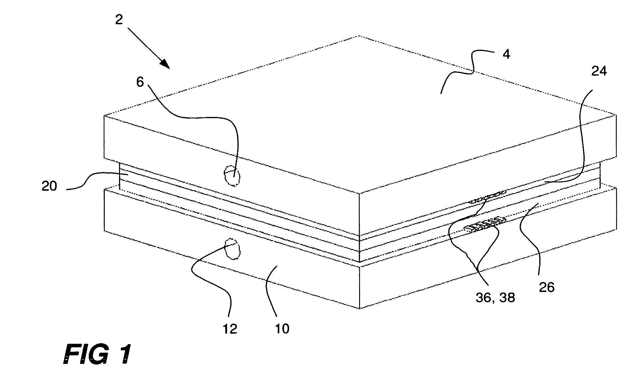
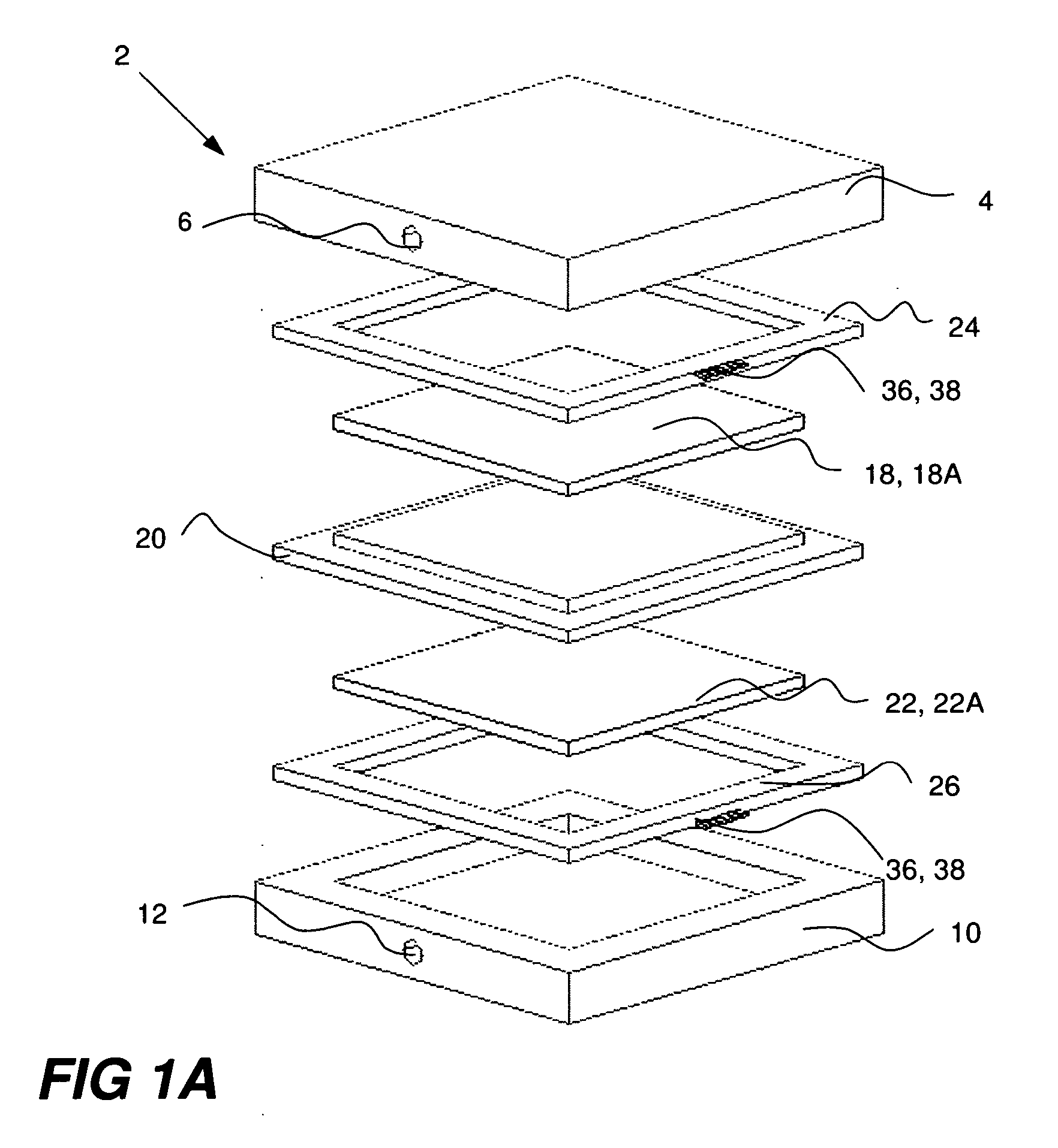
[0035] Although the invention can be used in many different high-temperature seal environments, the invention is particularly useful in applications that utilize glass or ceramic seals. One such application is the solid oxide fuel cell, and FIGS. 1-3 show an exemplary (and greatly simplified) construction of such a device. In particular, ...


PUM


Abstract

A high-temperature seal having in-situ integrity monitoring capability includes a quantity of dielectric material sealing an interface between adjacent structures and an electrical transmission line embedded within the dielectric material. A signal injection port is provided for exciting the transmission line with an excitation signal. One or more sample ports are provided for sampling the transmission line to obtain signal samples resulting from the excitation signal. The sample port(s) are adapted for connection to a signal analyzer adapted to analyze the signal samples for indications of seal integrity problems. Using a technique such as time domain reflectometry or frequency response analysis, the transmission line can be monitored for changes in characteristic impedance due to changes in seal dielectric constant and/or disruption of the transmission line. Such evaluation provides useful information for making determinations about seal integrity in a manner that permits safe seal operation and minimization of resultant stress modes.

Description

BACKGROUND OF THE INVENTION [0001] 1. Field of the Invention [0002] The present invention relates to high-temperature seals and their characteristics. More particularly, the invention concerns a technique for in-situ monitoring of seal integrity. [0003] 2. Description of Prior Art [0004] By way of background, various high-temperature device applications, such as solid oxide fuel cells, involve structures composed of multiple ceramic layers, or interleaved layers of ceramic and metal. To eliminate the possibility of gases (such as fuel constituents) prematurely mixing or leaking from interior regions of the structure, the ceramic-to-ceramic or ceramic-to-metal interfaces of adjacent layer pairs are typically joined and sealed together with a glass or ceramic seal. These seals must be capable of withstanding the high-temperature operating environment of the device over its operational lifetime. The seal materials must also be carefully matched with the adjacent layers in order to mini...

Claims


Application Information

Patent Timeline
IPC IPC(8): G01N33/00
CPCG01R31/11H01M8/0271Y02E60/525H01M2008/1293Y02E60/50H01M8/2425H01M8/0276
Inventor OLENICK, JOHN A.CURRY, TIMOTHY J.BOURDELAISE, ROBERT A.RICHARDS, ELI A.VICHOT, PAUL A.GRABOW, BARRY E.WILDERSON, SAMUEL F.
Owner ENRG
Why Eureka
Try Eureka