Robust maximum engine torque estimation

a maximum engine and torque estimation technology, applied in the direction of machines/engines, electric control, combustion engines, etc., can solve the problem of greater errors in engine torque estimation

Active Publication Date: 2007-03-08
FORD GLOBAL TECH LLC
View PDF9 Cites 72 Cited by
  • Summary
  • Abstract
  • Description
  • Claims
  • Application Information

AI Technical Summary

Benefits of technology

[0006] In this way engine torque may be estimated in a robust manner allowing for an engine control strategy to include different modes of operation in an engine system with an asymmetric exhaust gas...

Problems solved by technology

For example, in an engine system with an asymmetric exhaust sensor configuration, some modes of operation may cause the asymmetric s...

Method used


Image

  • Robust maximum engine torque estimation
  • Robust maximum engine torque estimation
  • Robust maximum engine torque estimation

Examples


Embodiment Construction

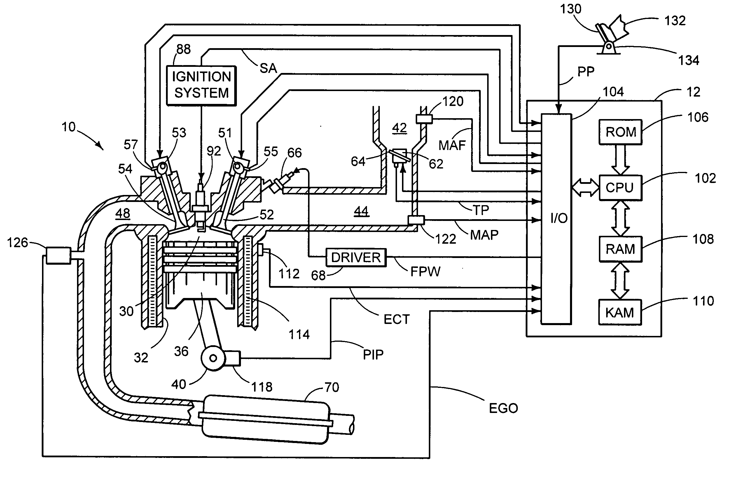
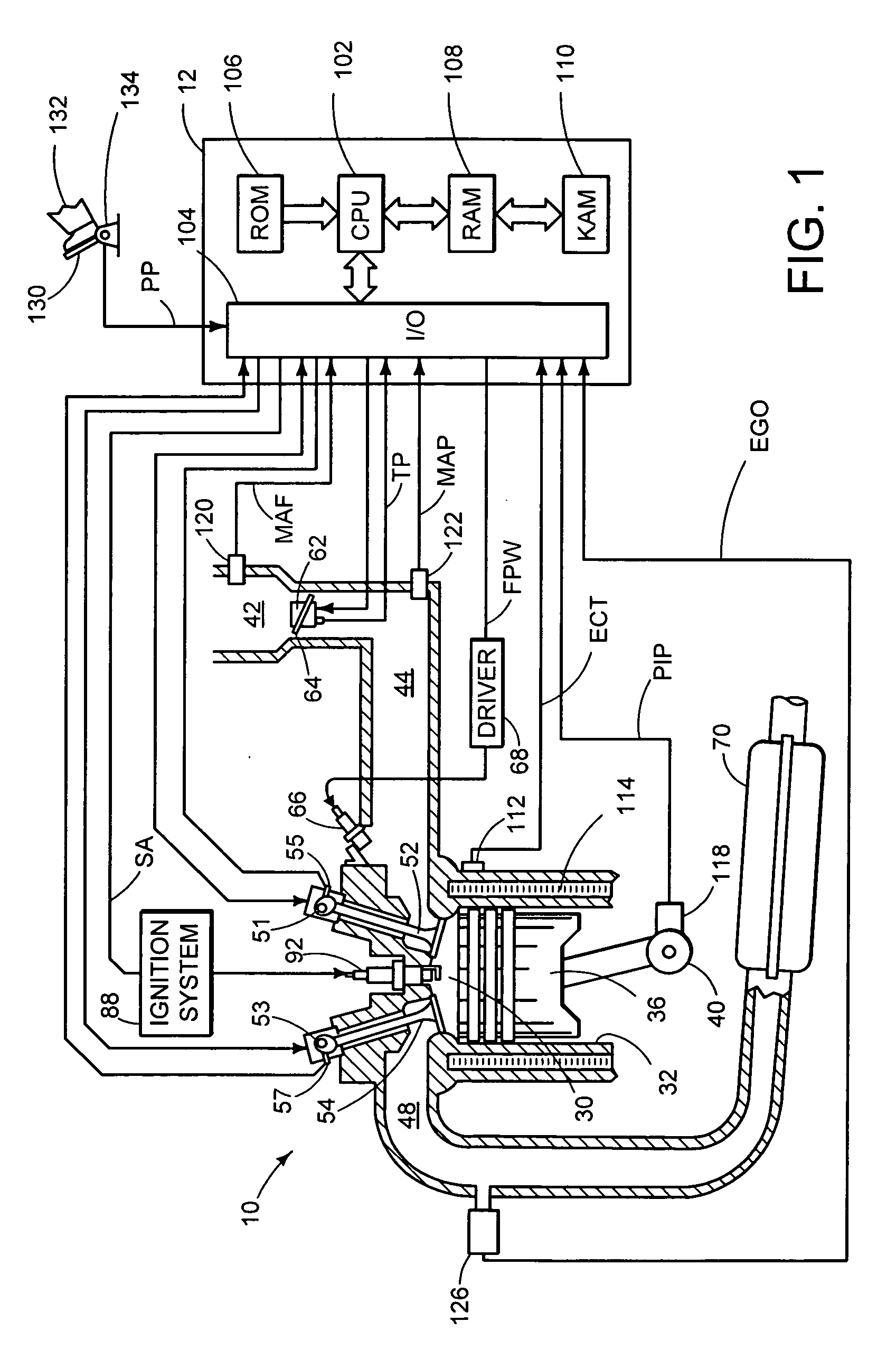
[0018]FIG. 1 shows a schematic diagram of one cylinder of multi-cylinder internal combustion engine 10. Combustion chamber or cylinder 30 of engine 10 is shown including combustion chamber walls 32 and piston 36 positioned therein and connected to crankshaft 40. A starter motor (not shown) may be coupled to crankshaft 40 via a flywheel (not shown). Cylinder 30 may communicate with intake port 44 and exhaust port 48 via respective intake valve 52 and exhaust valve 54. Intake valve 52 and exhaust valve 54 may be actuated via intake camshaft 51 and exhaust camshaft 53. Further, the position of intake camshaft 51 and exhaust camshaft 53 may be monitored by intake camshaft sensor 55 and exhaust camshaft sensor 57 respectively. In an exemplary embodiment, intake and exhaust valve control may be provided by signals supplied by controller 12 via electric valve actuation (EVA). Additionally intake and exhaust valve may be controlled by various other mechanical control systems including cam p...


PUM


Abstract

A system for a vehicle comprising of an engine including a first cylinder group and a second cylinder group; a linear exhaust gas sensor coupled exclusively to the first cylinder group; a switching exhaust gas sensor coupled exclusively to the second cylinder group; and a controller configured to operate the engine in at least a first mode and a second mode, where in the first mode the first and second cylinder groups combust air and fuel, where in the second mode at least one of the first and second cylinder groups combusts air and injected fuel and the other one of the first and second cylinder groups pumps air without injecting fuel, and where the controller is further configured to estimate torque of the engine in each of the first and second modes of operation based on the air-fuel ratio of the first cylinder group and the air-fuel ratio of the second cylinder group independent of the switching sensor and dependent on the linear sensor.

Description

[0001] This application claims priority to U.S. Provisional Application No. 60 / 713,891, filed Sep. 2, 2005, the entire contents of which are incorporated herein by reference.BACKGROUND AND SUMMARY [0002] Some engine control strategies may estimate torque based on air-fuel ratio and other operating parameters in order to control engine output. Furthermore, some engine control strategies advantageously employ different modes of engine operation, such as for example, a fuel injector cut-out mode which may include a cylinder group that pumps air without injected fuel in order to improve fuel economy and engine efficiency. [0003] One approach attempts to estimate engine torque based on various parameters including the air-fuel ratios of the cylinders combusting air and fuel in a fuel injector cut-out mode. See, for example, U.S. Pat. No. 6,758,185. [0004] However, the inventors herein have recognized that this approach may have some disadvantages. For example, in an engine system with an...

Claims


Application Information

Patent Timeline
IPC IPC(8): F02D41/00F02D17/02F02B17/00F02D7/00
CPCF02D17/02F02D41/0082F02D41/1443F02D2200/1004F02D41/1456F02D41/1497F02D41/1454
Inventor PALLETT, TOBIASSURNILLA, GOPICHANDRAKERNS, JAMES
Owner FORD GLOBAL TECH LLC
Why Eureka
Try Eureka