Built-in attachment device using selective laser sintering

Active Publication Date: 2007-03-08
NORTHROP GRUMMAN SYST CORP
View PDF14 Cites 54 Cited by
  • Summary
  • Abstract
  • Description
  • Claims
  • Application Information

AI Technical Summary

Benefits of technology

[0010] In the alternative, only the salient features of the attachment device may be integrally formed with the part. For example, the salient features of the nut plate discussed above are a pair of retaining opening formed in the sidewalls. The retaining openings receive a pair of corresponding spring clips of the nut. It is the engagement between the nut spring clip and the sidewall retaining openings which captures th

Problems solved by technology

Once the pipes are joined together, they are typically disassembled and reassembled during maintenance or failure.
In a large pipe system, the number of bolts and nuts may be enormous such that keeping track of all the nuts and bolts is too difficult o

Method used


Image

  • Built-in attachment device using selective laser sintering
  • Built-in attachment device using selective laser sintering
  • Built-in attachment device using selective laser sintering

Examples


Embodiment Construction

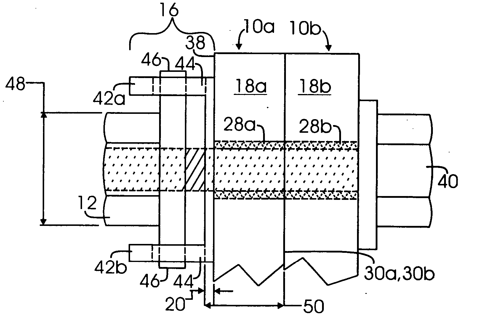
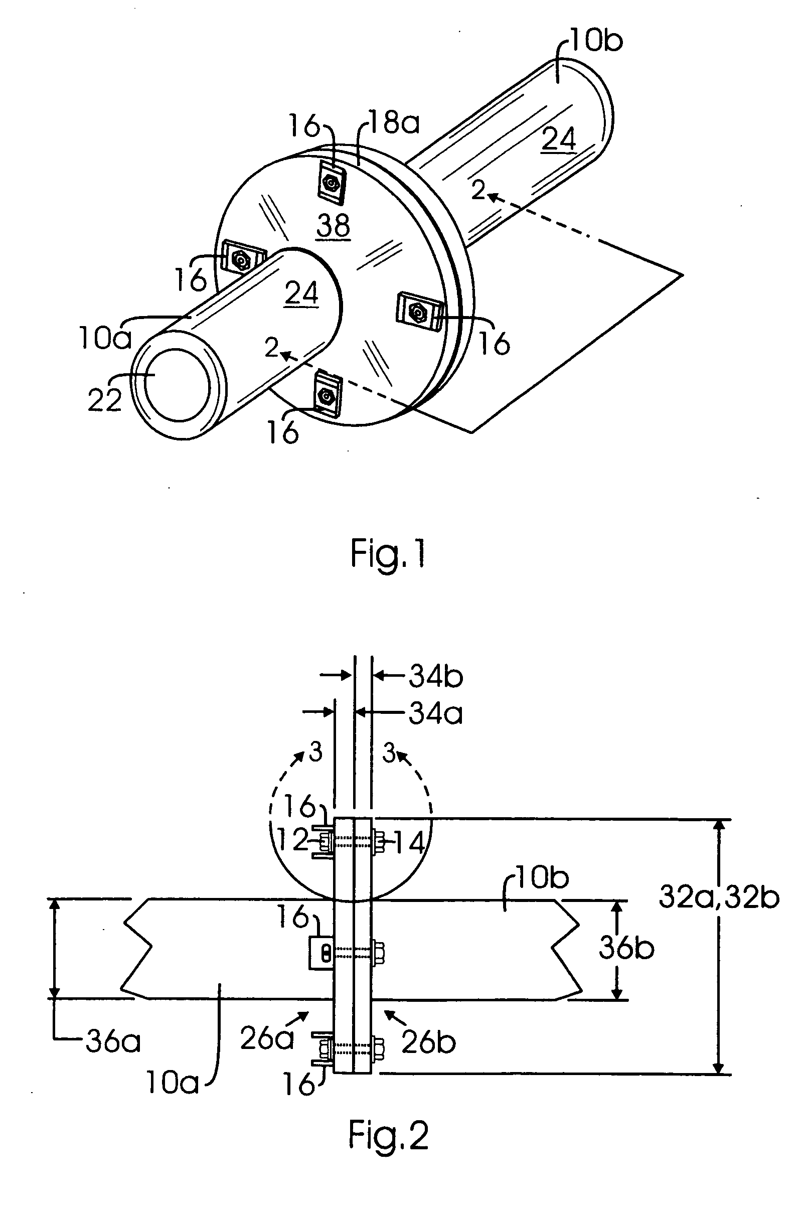
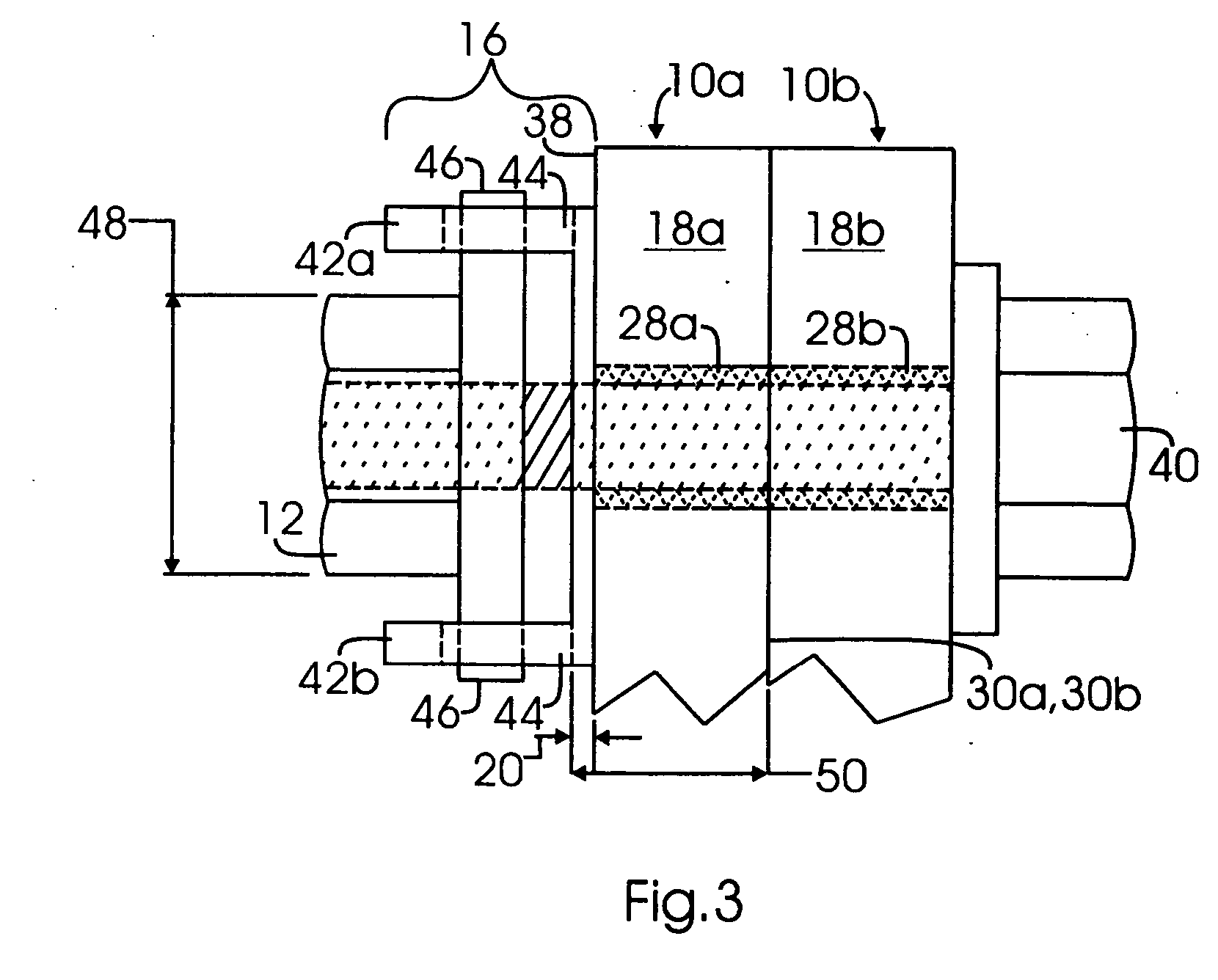
[0020] The drawings referred to herein are for the purposes of illustrating the various aspects of the present invention and are not meant to limit the scope of the present invention. FIG. 1 illustrates two pipes 10a, 10b which have been joined together via sets of nuts 12 (see FIG. 2) and bolts 14 (see FIG. 2). The nuts 12 are inserted into nut plates 16 (see FIGS. 1-3) which are integrally formed with the pipe 10a. FIG. 3 illustrates a flange 18a of pipe 10a. The nut plates 16 retain the nuts 12 in the nut plates 16 such that the nuts 12 are not lost when the pipes 10a, 10b are disassembled.

[0021] The integral formation of the nut plates 16 with the pipe 10a reduces the time to initially assemble the system of pipes 10a, 10b. The reason is that the time to attach the nut plate 16 to the pipe 10a is eliminated or not required to initially assemble the pipe system 10a, 10b. Additionally, the integral formation of the nut plates 16 with the pipe 10a forms a pipe that has a greater s...


PUM


Abstract

A method of assembling a first part and a second part. The method may comprise the step of integrally forming an attachment device and a first part. For example, the attachment device may be a nut plate operative to retain a nut therein, and the first part may be an air duct. The nut plate and the air duct may be integrally formed via selective laser sintering or stereo lithography such that the nut plate is an integral feature of the air duct. A nut may be retained in the nut plate, and a mating bolt may engage the nut to attach the air duct (i.e., the first part) to the second part.

Description

CROSS-REFERENCE TO RELATED APPLICATIONS [0001] Not Applicable STATEMENT RE: FEDERALLY SPONSORED RESEARCH / DEVELOPMENT [0002] Not Applicable BACKGROUND OF THE INVENTION [0003] The present invention relates to forming a part with an integrally formed attachment device via selective laser sintering or the like. [0004] Prior art pipes may be fabricated with flanges which are bolted together with nuts and bolts. In particular, the flanges of two mating prior art pipes may have a plurality of bolt holes about a periphery of the flanges. The bolt holes of a first pipe flange correspond, or otherwise, have the same pattern of bolt holes as the flange of a second pipe. The pipe flanges of the first and second pipes are aligned to each other, and bolts are inserted through the bolt holes and screwed onto a nut. The bolts and nuts apply clamping pressure onto the flanges to join the pipes together. [0005] Once the pipes are joined together, they are typically disassembled and reassembled during...

Claims


Application Information

Patent Timeline
IPC IPC(8): B23K26/00
CPCB29C67/0077B29K2077/00B29K2025/00B29C64/153B33Y10/00B33Y80/00B33Y70/00
Inventor HUSMANN, CHRISTOPHERSTEIN, GREGORY
Owner NORTHROP GRUMMAN SYST CORP
Why Eureka
Try Eureka