Ink tank and recording apparatus using ink tank
a technology of ink tank and recording apparatus, which is applied in the direction of mixing, printing, mixing, etc., can solve the problems of inability to increase the swing range of the stirrer, the width of the ink tank is limited to a relatively small value, and the difficulty in maintaining the quality of dye ink for outdoor printed materials, etc., to achieve efficient agitation of ink and high quality
- Summary
- Abstract
- Description
- Claims
- Application Information
AI Technical Summary
Benefits of technology
Problems solved by technology
Method used
Image
Examples
first exemplary embodiment
[0036] Structure of Ink Tank
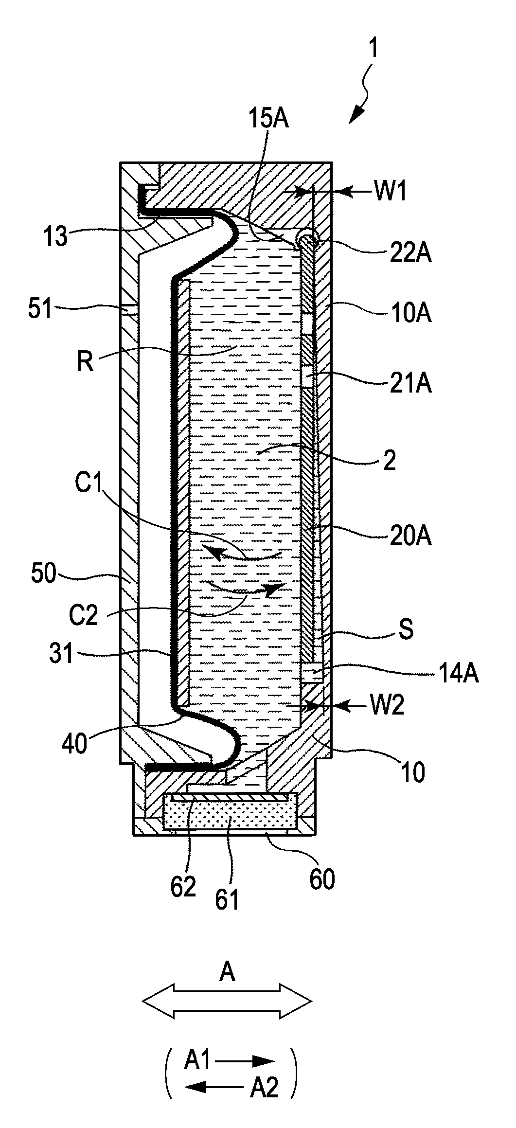
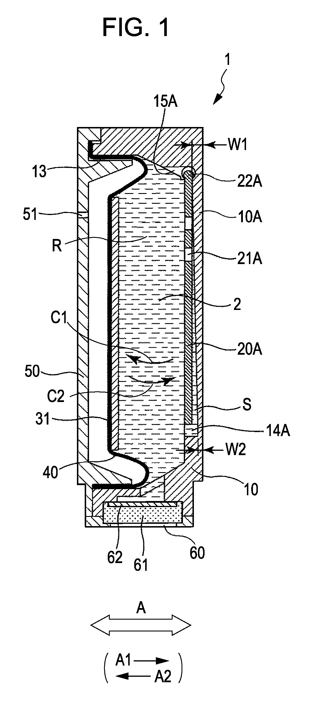
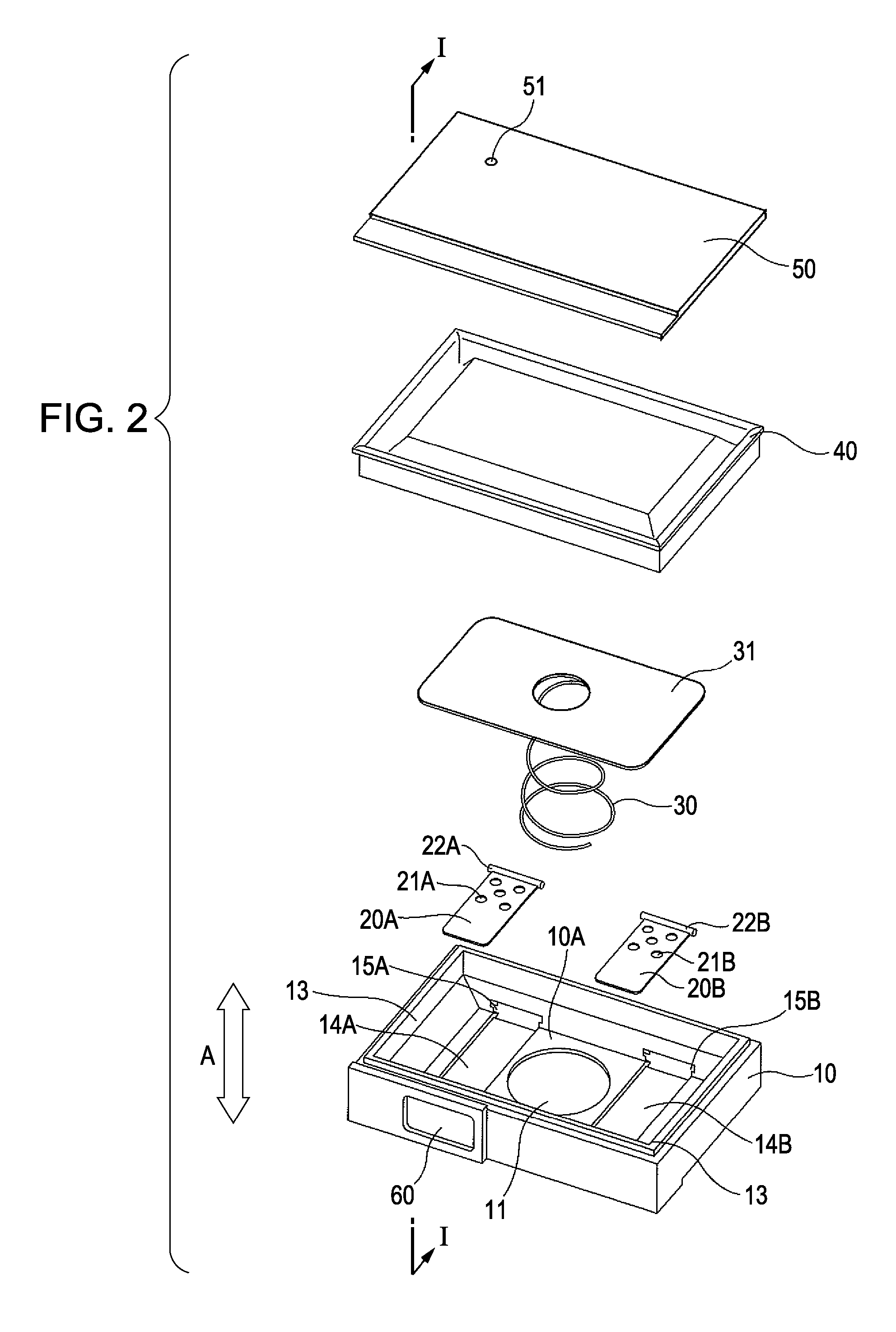
[0037]FIG. 1 is a cross-sectional view of an ink tank 1 according to a first embodiment of the present invention. FIG. 2 is an exploded perspective view of the ink tank 1. FIG. 1 corresponds to a cross-sectional view taken along line I-I of FIG. 2.
[0038] The ink tank 1 is a container in which an ink container R formed from a tank case 10 and a flexible member 40 is filled with ink 2. As shown in FIG. 1, the ink tank 1 is mounted to an inkjet recording apparatus with an ink supply port 60 facing downward. The ink supply port 60 is connected to an ink supply channel of an inkjet recording head, which will be described below. According to the present embodiment, the ink tank 1 can be removed from the recording head. However, the ink tank 1 may be irremovably integrated into the recording head.
[0039] As shown in FIG. 2, the ink tank 1 includes the tank case 10, stirrers 20A and 20B, a spring 30, a pressing plate 31, the flexible member 40, and a cover 50. ...
second exemplary embodiment
[0072]FIG. 10 is a cross-sectional view of an ink tank according to a second embodiment of the present invention.
[0073] According to the second embodiment, when, as shown in FIG. 10, the ink tank is disposed with an ink supply port 60 facing downwards, pivot shafts 22C and 22D of stirrers 20C and 20D are supported by supporting portions 15C and 15D so as to be swingable about a substantially vertical axis. Basically, the supporting portions 15C and 15D and the pivot shafts 22C and 22D are similar to the above-described supporting portions 15A and 15B and pivot shafts 22A and 22B, respectively. However, mounting positions thereof are different. A plurality of through-holes 21C and 21D are formed in the stirrers 20C and 20D at positions adjacent to the pivot shafts 22C and 22D, respectively. Like the first embodiment, the ink tank reciprocally moves in a main scanning direction indicated by arrow A together with a carriage 153. Thus, the inertia force causes stirrers 20C and 20D to s...
third exemplary embodiment
[0074]FIG. 11 is a cross-sectional view of an ink tank 1 according to a third embodiment of the present invention.
[0075] In the above-described embodiments, the ink tank 1 has a structure in which a predetermined negative pressure is maintained in the ink container R using a negative pressure control mechanism including the flexible member 40 and the spring 30. According to the third embodiment, the ink tank 1 includes an outside-air intake mechanism for controlling the pressure in the ink container R to be a predetermined negative pressure. The outside-air intake mechanism draws the outside air into the ink container R so as to maintain the pressure in the ink container R to be a predetermined negative pressure with respect to the atmosphere. For example, the outside-air intake mechanism may have a structure in which a small gap is provided to the bottom surface of the ink tank 1 and the meniscus formed by the ink in the gap causes the pressure in the ink container R to be negativ...
PUM
 Abstract
Description
Claims
Application Information
 - R&D
- Intellectual Property
- Life Sciences
- Materials
- Tech Scout
- Unparalleled Data Quality
- Higher Quality Content
- 60% Fewer Hallucinations
Browse by: Latest US Patents, China's latest patents, Technical Efficacy Thesaurus, Application Domain, Technology Topic, Popular Technical Reports.
© 2025 PatSnap. All rights reserved.Legal|Privacy policy|Modern Slavery Act Transparency Statement|Sitemap|About US| Contact US: help@patsnap.com


