Network load balancing apparatus, systems, and methods

a network load and load balancing technology, applied in the field of computer network systems, can solve problems such as inability to receive orders, and under-utilization of the total available bandwidth

Inactive Publication Date: 2007-03-08
TAHOE RES LTD
View PDF7 Cites 90 Cited by
  • Summary
  • Abstract
  • Description
  • Claims
  • Application Information

AI Technical Summary

Problems solved by technology

Out of order reception may occur because of variable and unequal delays associated with the elementary links.
These delays may be caused by differential trace lengths, by traversing buff...

Method used


Image

  • Network load balancing apparatus, systems, and methods
  • Network load balancing apparatus, systems, and methods
  • Network load balancing apparatus, systems, and methods

Examples


Embodiment Construction

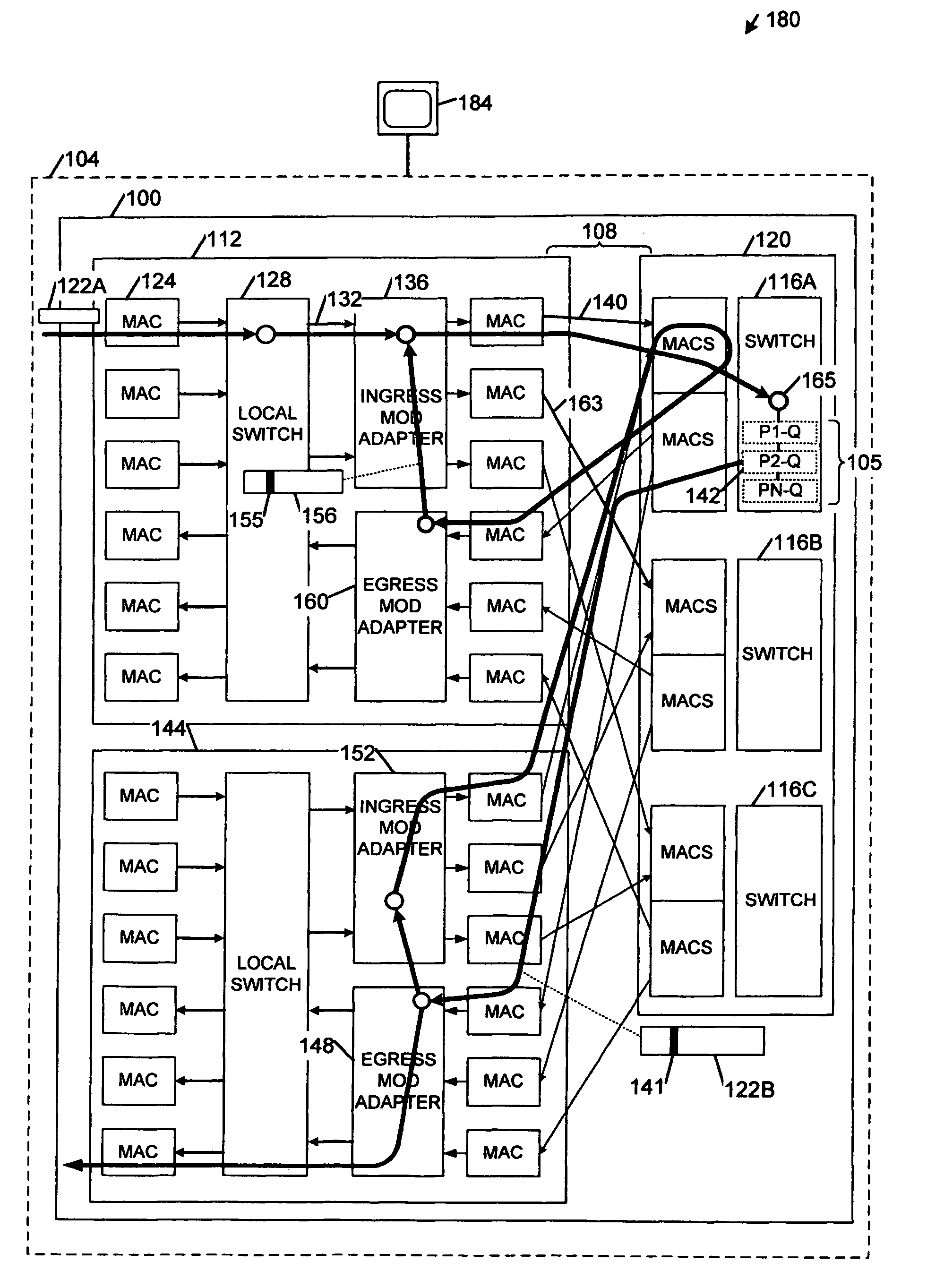
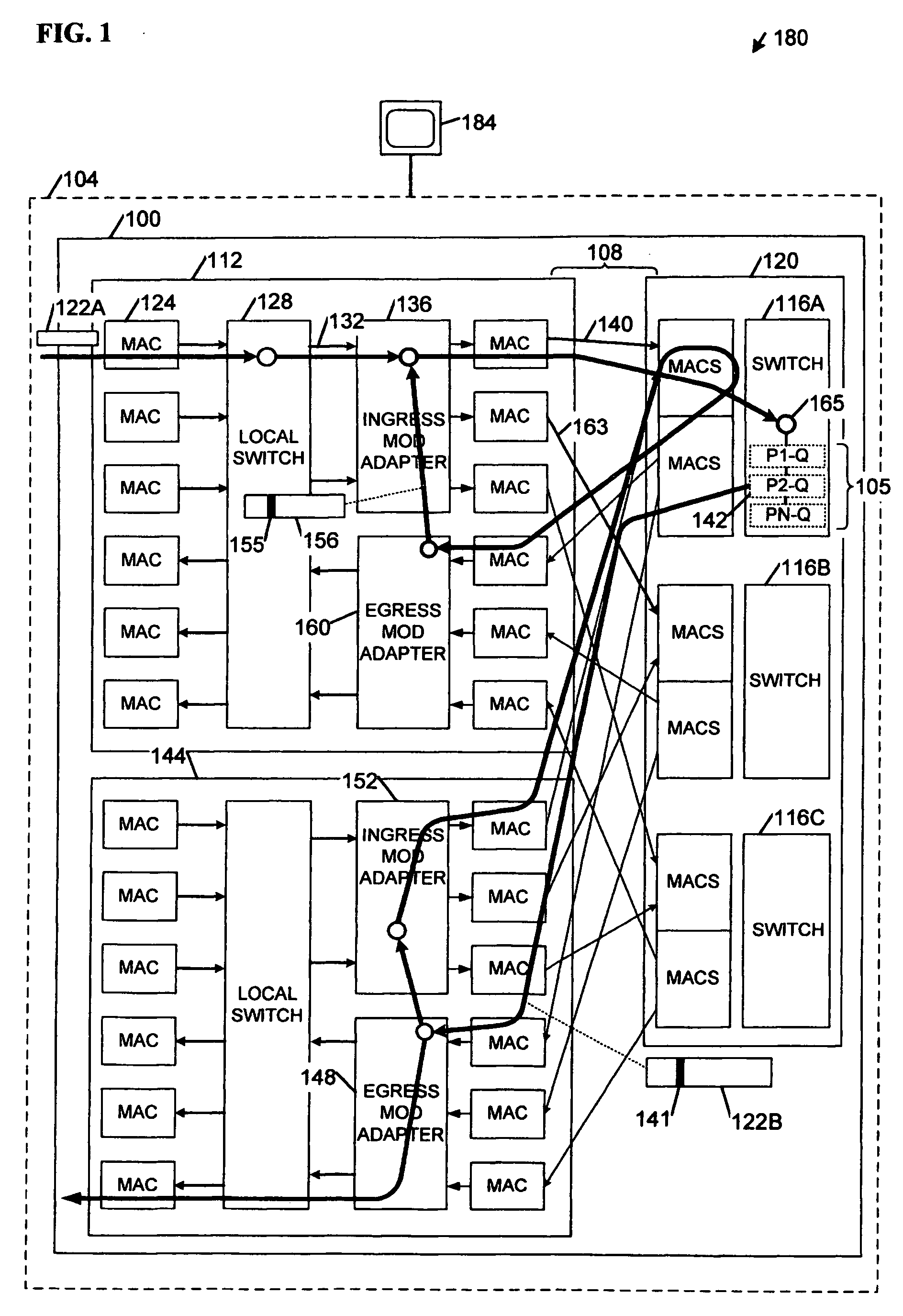
[0009]FIG. 1 comprises a block diagram of an apparatus 100 and a system 180 according to various embodiments of the invention. Some embodiments may comprise a network switch 104, including perhaps a dynamically load-balanced switch. Levels of queues 105 inside the switch 104 may be indicative of loading on connections within the switch 104. The queue levels may result from overall traffic patterns and from a mix of traffic of different priorities from various line cards within the switch 104. Because traffic patterns and the priority mix may change over time, a load associated with a given connection may change. Switching efficiencies may be enhanced if internal load balancing functions dynamically adapt to changes in loads on the internal connections. Ingress and egress points and / or line cards referred to hereinafter are intended to convey a direction of packet traffic flow. That is, traffic may flow into the network switch 104 through an ingress line card 112 and flow out of the ...


PUM


Abstract

Apparatus, systems, methods, and articles described generally herein may receive a first packet marked with a congestion indicator (CI). Upon receipt of the CI, a load-balancing operation may be performed among a plurality of physical links upstream from a point of congestion to alleviate the congestion. Other embodiments may be described and claimed.

Description

TECHNICAL FIELD [0001] Various embodiments described herein relate to computer networking systems generally, including apparatus, systems, and methods used to perform interconnect load balancing within a network. BACKGROUND INFORMATION [0002] Existing Ethernet standards including Institute of Electrical and Electronic Engineers (IEEE) 802.3AD-2000 IEEE Standard for Information Technology—Local and Metropolitan Area Networks—Part 3: Carrier Sense Multiple Access with Collision Detection (CSMA / CD) Access Method and Physical Layer Specifications—Aggregation of Multiple Link Segments (2000) may define ways to aggregate multiple Ethernet links to behave as a single entity. Link aggregation may enable higher layer protocols to communicate between two points connected by several lower capacity links (“elementary links”) as if the two points were connected by a higher capacity link. According to 802.3ad methods, packets contributing to an aggregate bandwidth may be divided across the multip...

Claims


Application Information

Patent Timeline
IPC IPC(8): H04J1/16
CPCH04L47/10H04L47/11H04W28/08H04L47/14H04L47/31H04L47/125H04W28/02H04W8/04
Inventor HO, MICHAELWADEKAR, MANOJ
Owner TAHOE RES LTD
Why Eureka
Try Eureka