[0056]
Toolbar 408 includes icons for enabling various features, including settings icon 420,
panic icon 422, sub-group chat icon 424, desktop program icon 426, docking / undocking icon 428, and exit icon 430. Setting icon 420 allows users to alter settings, including, for example, chat, video and name display settings.
Panic icon 422 sends a
panic alert message to other users at network communication devices. Sub-group chat icon 424 allows formation of a sub-group of network
communication device users who can engage in a confidential chat. Desktop program icon 426 allows users to open other programs, such as Microsoft Word. Dock / undock icon 428 allows users to combine and separate the three activity areas. Exit icon 430 shuts down the core application process.
[0057]
Navigation bar 410, which may be located on each of the three activity areas, allows users to move the activity areas to other areas of the display screen. A network
communication device user clicks on undock / dock icon 428 and uses
navigation bar 410 to drag each activity area to the desired location of the display screen. Additionally,
navigation bar 410 can be used to minimize
user interface 400 to work on other
software programs, by clicking on minimize button 434.
Navigation bar 410 also allows users to close
user interface 400 by clicking on terminate button 436.
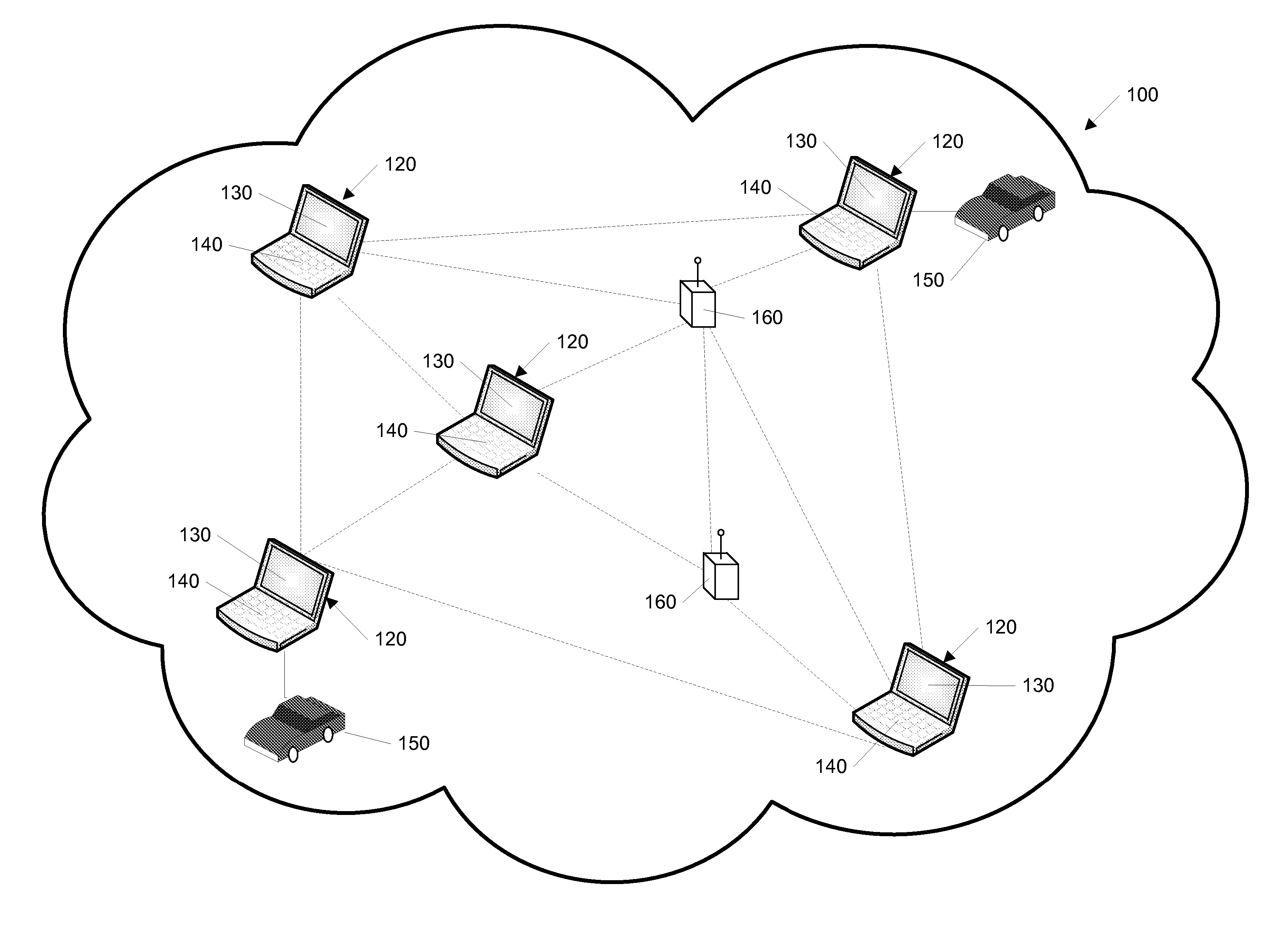
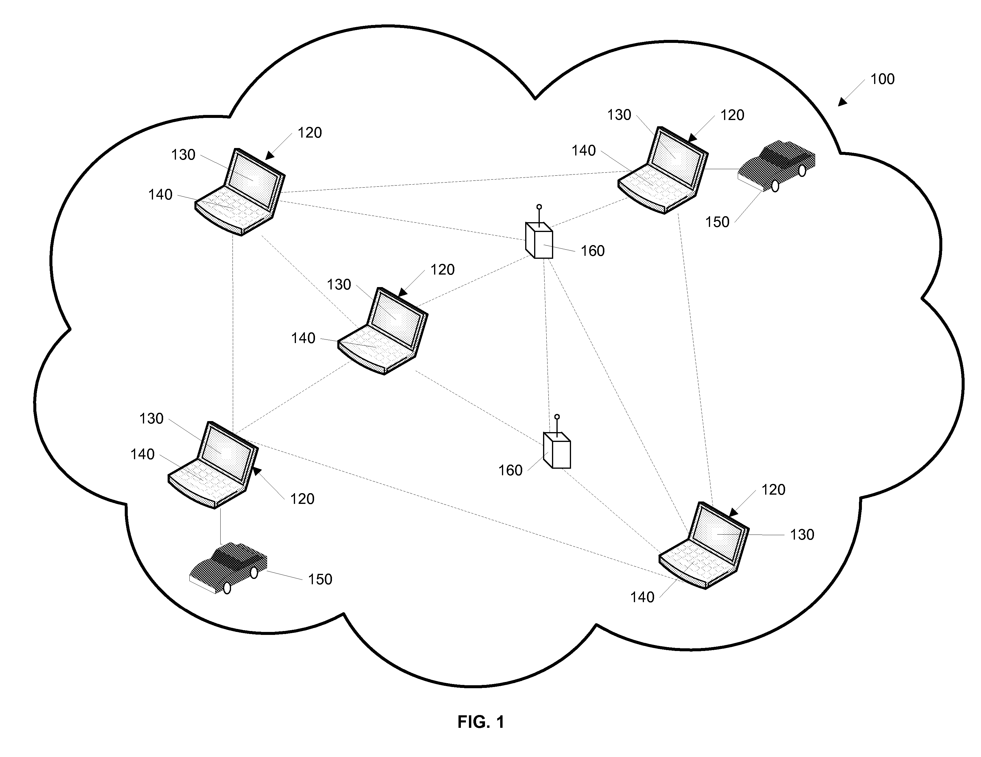
[0071] Having the capability to send and receive audio and video data to and from any network
communication device 120 user is also helpful to orchestrating and executing team oriented tasks. The network communication device enables
peer to peer communication through voice /
video chat activity area 406, shown in FIG. 4. Audio communication is accomplished through a continuous
stream of data over a consistent connection while video communications involve sending of discreet packets or bursts of information. Since audio and video rely on different data streams, network communication device users can connect to one without the other. In addition to communication between remote network communication devices, cameras or microphones may be placed in remote connections and connected to the network, thereby allowing monitoring of predetermined areas for safety and other purposes.
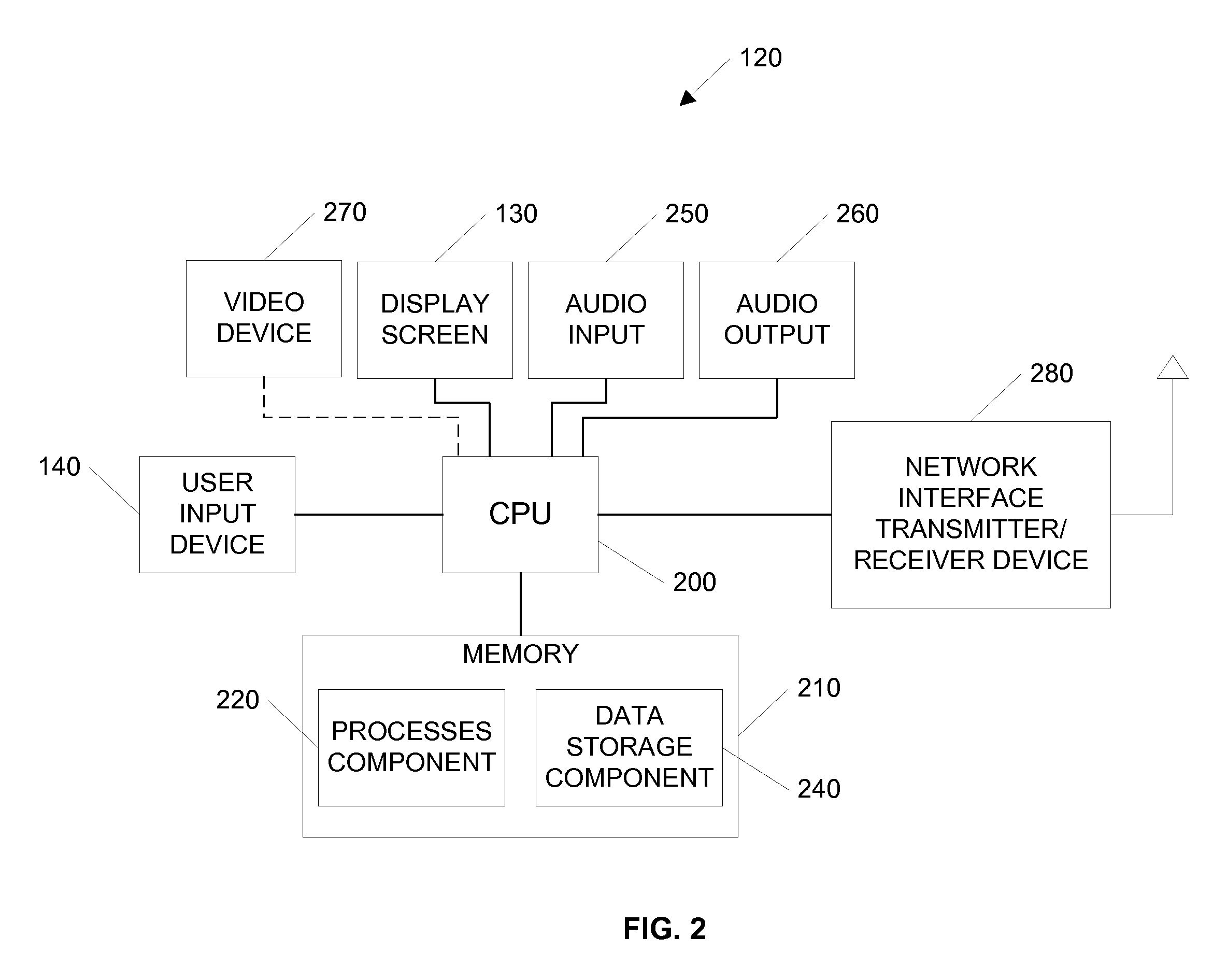
[0078] The process for establishing audio connection is shown in FIG. 12A. In step 1202, a remote on line user is selected for an audio communication connection. After connector 450, FIG. 4, is clicked, in step 1204, the requesting network communication device checks the capabilities of the remote user in its data storage component 240, FIG. 2, ascertaining whether audio capability is enabled for the select user. If audio capability is present, in step 1206, a message is sent through audio input / output filter 352 of the network communication device for the sender, authorizing sending of an audio connection packet to the remote user. In step 1208, FIG. 12A, the audio connection packet is sent to the network communication device 120 of the remote user. In step 1210, FIG. 12A, incoming packet queuing process 322 of the remote user receives the packet and sends it to packet filter process 324, which ascertains its purpose. Remote users can block requests for audio connection by disconnecting connector 450 or by disabling broadcast local audio enabler 462 and remote audio enabler 466. Assuming both devices remain audio enabled, in step 1210, a secure
network connection is established and streaming audio can occur over a
transmission control protocol (“TCP”) in step 1212, FIG. 12A, with audio capture 350 obtaining audio streams from remote users. Compression and amplification filters 354 and 356 respectively reduce the number of bits sent over the network and clarify audio transmission.
Network communication devices 120 may, for example, rely on Voice over
Internet Protocol (VoIP) for audio communication, though other methodologies may be employed.
[0079] The process for establishing video connection is shown in FIG. 12B. Similar to audio connection, once a user clicks connector 450, FIG. 4, to select, in step 1202, FIG. 12B, a remote user for video contact, the requesting network communication device 120, FIG. 1, checks the data storage component to ascertain whether a remote user is video capability enabled, in step 1216. If video capability is present, in step 1218, FIG. 12B, a message is sent through video display process 370 of the sender network communication device, authorizing sending of the video connection packet to the remote user. In step 1220, FIG. 12B, the video connection packet is sent to the network communication device 120 of the remote user. In step 1222, incoming packet queuing process 322 of the remote user receives the packet and sends it to packet filter process 324, which ascertains its purpose. Remote users can block requests for video connection by disconnecting connector 450 or by disabling broadcast local video enabler 464. In step 1224, FIG. 12B, video connection is established. Assuming both devices remain video enabled, in step 1226, a request for a video frame is issued by the video display process of the sender and remote user network communication devices 120. The requesting network communication device sends a single video frame to the remote network communication device along with a request for a frame of video from the remote device. The remote network communication device receives the frame, processes the received frame and responds to the request by sending its own single video frame back. As these single frames are being sent back and forth, a second video frame is concurrently written by each device. Once the second frame is written, a third frame overwrites the first. In other words, once the
system finishes writing a frame, it is sent and cleared to make way for the writing of a new video frame, which, in turn is forwarded among the communicating users. This asynchronous transfer of data is repeated. In this way, a secure
network connection is established and video transfer occurs over UDP. The network communication devices 120 may employ a frame-by-frame streaming
JPEG format, which preserves
video quality, even if network connections are interrupted.
