Clock transmission apparatus for network synchronization between systems

a technology of transmission apparatus and network synchronization, which is applied in the direction of electrical apparatus, digital transmission, synchronization signal speed/phase control, etc., can solve the problems of single communication cable, synchronization apparatus, waste, etc., and achieve high accuracy

Inactive Publication Date: 2007-03-08
WABCO AUTOMOTIVE (UK) LTD +2
View PDF5 Cites 9 Cited by
  • Summary
  • Abstract
  • Description
  • Claims
  • Application Information

AI Technical Summary

Benefits of technology

[0023] To achieve the above object, the present invention allows network synchronization to be maintained between two systems using a cheap UTP. (Unshielded Twisted Pair) without using a costly GPS system (an apparatus for maintaining network synchronization of a high accuracy between the two systems) and an expensive transmission line (an optical cable or a coaxial cable).

Problems solved by technology

Generally, if a common base station is installed in a region where the number of subscribers is relatively smaller than the number of subscribers covered by a base station, waste occurs.
However, the conventional network synchronization apparatus between the remote unit and the main unit has the following problems.
Thus, there is a limitation in that a single communication cable cannot be used.
Also, there is a disadvantage that an expensive communication cable such as an optical cable and a coaxial cable has to be used in terms of accuracy in clock transmission.
In addition, the second type network synchronization apparatus employing the GPS receiver has a disadvantage that a costly GPS receiver is used, and hence the price of the system is increased.
More particularly, with rapid development of communication markets, if the same function is performed in the same solution under the circumstances where the system has been competitively developed, lots of limitations occurs such as the demand for development of a lower price system.

Method used


Image

  • Clock transmission apparatus for network synchronization between systems
  • Clock transmission apparatus for network synchronization between systems
  • Clock transmission apparatus for network synchronization between systems

Examples


Embodiment Construction

[0027] Now, an explanation of the preferred embodiment of the present invention will be given hereinafter with reference to accompanying drawings.

[0028] The present invention will now be described in detail in connection with preferred embodiments with reference to the accompanying drawings.

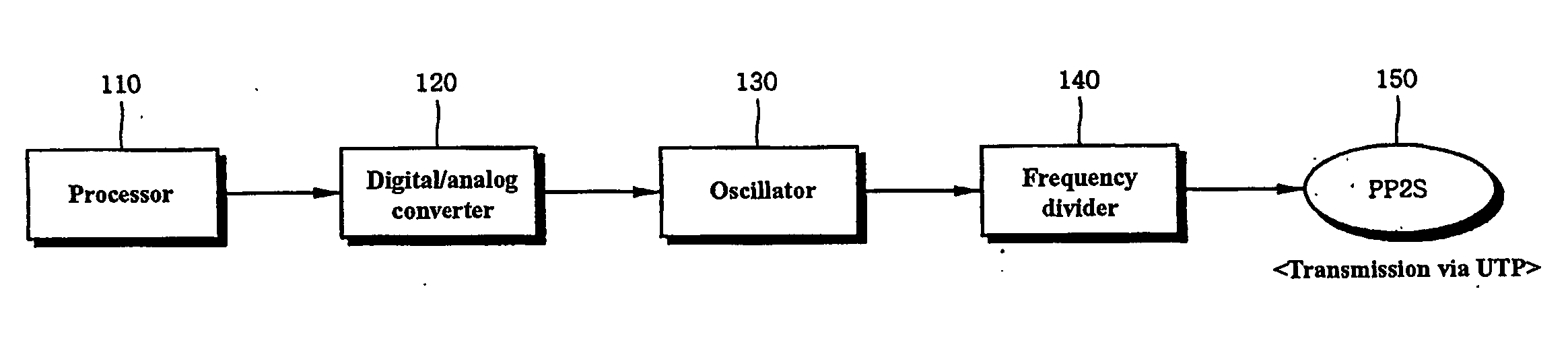
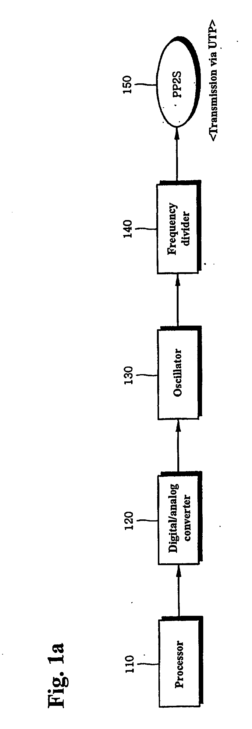
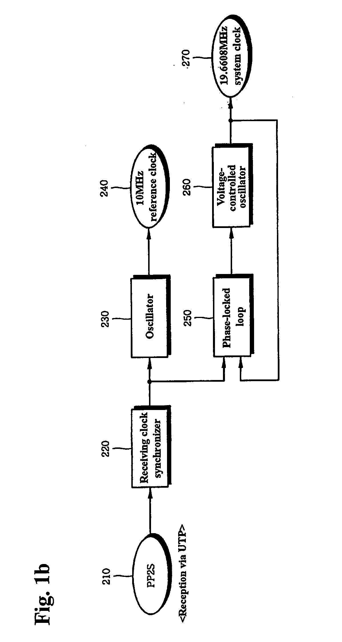
[0029] The present invention allows network synchronization to be achieved between two systems using a cheap unshielded twisted pair (hereinafter, referred to as “UTP”) without using a costly GPS system (an apparatus for maintaining network synchronization of a high accuracy between the two systems) and an expensive transmission line (an optical cable or a coaxial cable).

[0030] To this end, according to the present invention, network synchronization is maintained between a main unit (MU) and a remote unit (RU) by means of PP2S (a pulse every 2-second period, also referred to as “even-second”).

[0031] The concept of the present invention will be described in brief hereinafter. In order to send ...


PUM


Abstract

The present invention discloses a clock transmission apparatus for network synchronization between systems wherein a main unit generates a even-second (PP2S) pulse and transmits it to a remote unit and the remote unit uses the received PP2S to generate a system clock and a 10 MHz clock, whereby network synchronization is accomplished between two systems (the main unit and the remote unit). The main unit generates a reference clock, multiplexes the reference clock in a predetermined period to generate an even-second network synchronization clock, and then sends the even-second network synchronization clock to the remote unit using an UTP. Further, the remote unit generates a reference clock and a system clock based on the even-second network synchronization clock received through the UTP. Network synchronization can be maintained between two systems using a cheap UTP (Unshielded Twisted Pair) without using a GPS system (an apparatus for maintaining network synchronization of a high accuracy between the two systems) and an expensive transmission line (an optical cable or a coaxial cable).

Description

BRIEF DESCRIPTION OF THE DRAWINGS [0001]FIG. 1a and FIG. 1b are block diagrams showing the construction of a clock transmission apparatus for network synchronization between systems according to the present invention, wherein FIG. 1a shows a clock transmission apparatus in a main unit and FIG. 1b shows a clock receiving and generating apparatus in a remote unit.[0002]<Reference Numerals of Essential Elements in the Drawings>[0003]110: Processor [0004]120: Digital / Analog Converter [0005]130, 230: Oscillator [0006]140: Frequency Divider [0007]150, 210: PP2S [0008]220: Receiving Clock Synchronizer [0009]250: Phase-Locked Loop [0010]260: Voltage-Controlled Oscillator TECHNICAL FIELD [0011] The present invention relates to a clock transmission apparatus for network synchronization between two systems. More particularly, the present invention relates to a clock transmission apparatus for network synchronization between systems wherein in a communication system (especially, a very sm...

Claims


Application Information

Patent Timeline
Patent Type & Authority Applications(United States)
IPC IPC(8): H04L7/00H04J3/06H04L29/06
CPCH04J3/0638H04J3/0685H04L69/28H04L7/08H04L7/044H04L7/00
Inventor KIM, SEUNG YOU
Owner WABCO AUTOMOTIVE (UK) LTD
Why Eureka
Try Eureka