
Camera support and mounting assembly

Inactive Publication Date: 2007-03-08
PELCO INC
View PDF29 Cites 34 Cited by
  • Summary
  • Abstract
  • Description
  • Claims
  • Application Information

AI Technical Summary

Benefits of technology

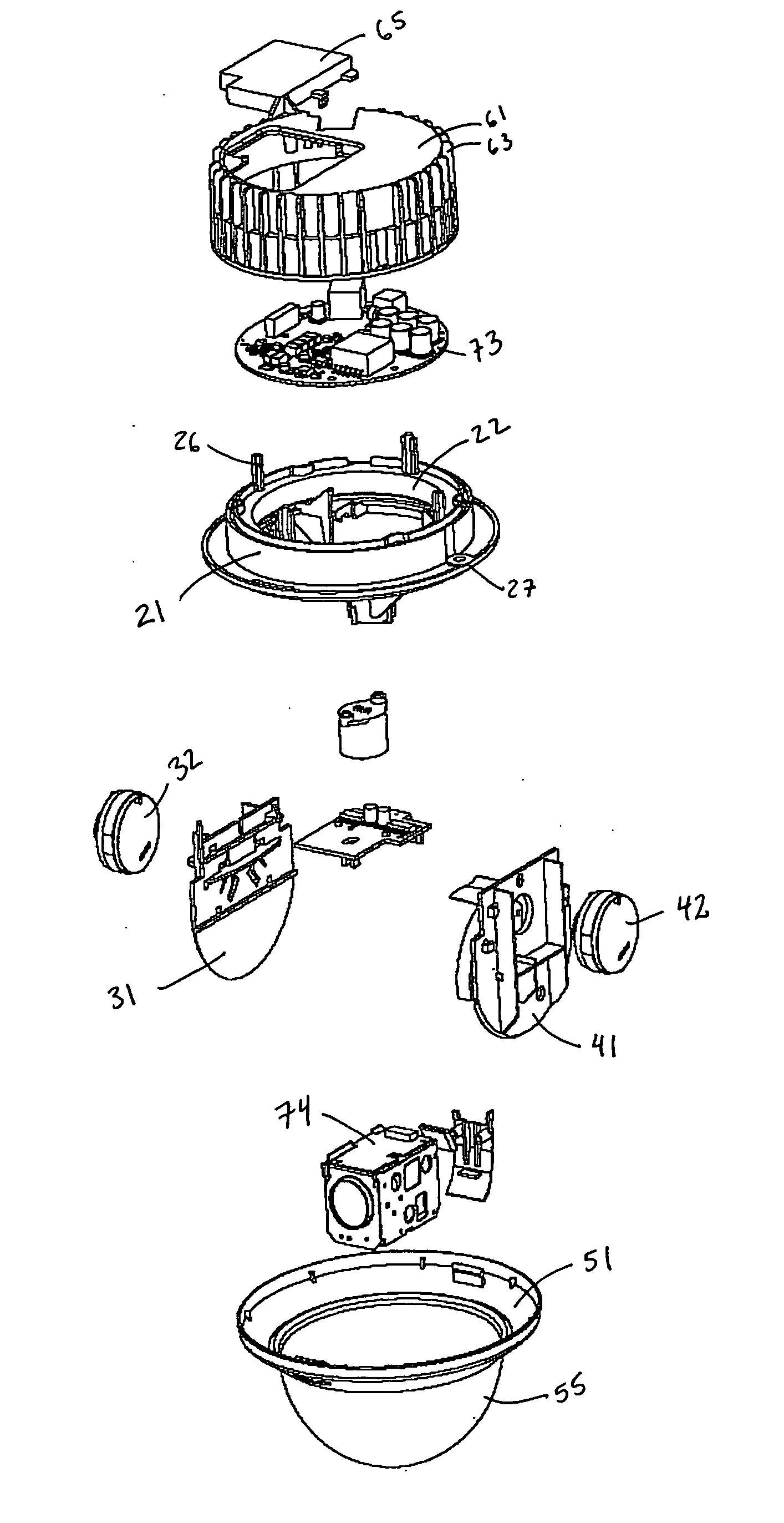
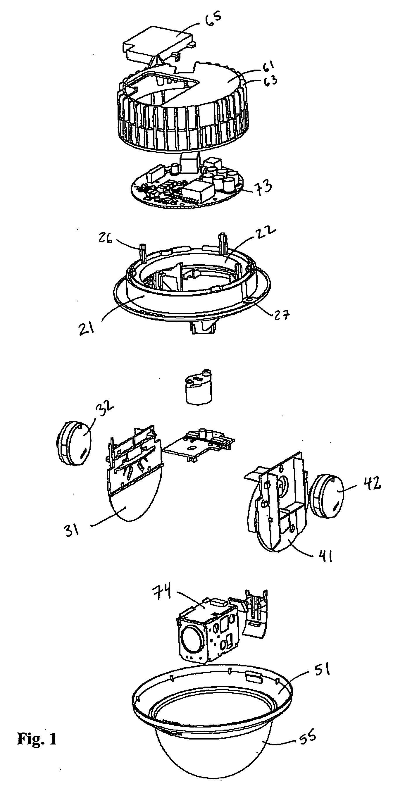
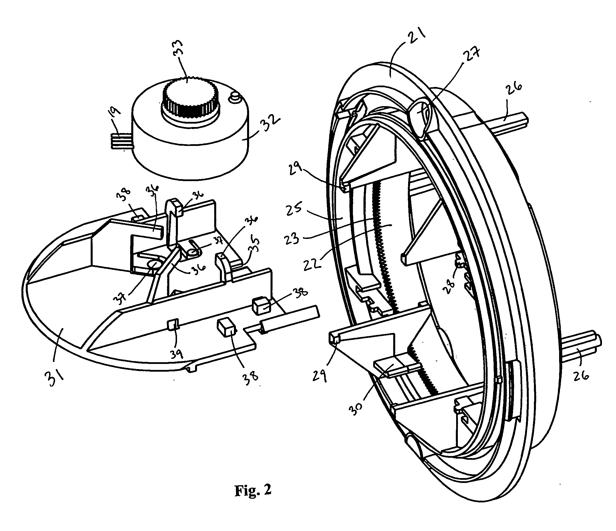
[0009] The present invention is a CCTV or surveillance camera mounting structure and enclosure that is made up of a minimal number of parts that are attached together using tension, clips and / or snap fit without the use of hardware or fasteners. At least one motor is mounted to a support bracket using a combination of locking tabs, boss registers, clips and / or tension members. One or more pins or registers on the motor correspond to openings or slots on the support bracket for precise positioning of the motor when attached to the bracket. The motor support bracket is, in turn, attached to a rotatable ring that moves in a base using a separate combination of locking tabs, boss registers, clips and / or tension members. One or more positioning tabs and / or slots on the motor bracket further assure that the bracket is properly and precisely mounted to the ring. Such a bracket is provided for the pan or scan motor which rotates the camera about a first axis, and a separate bracket is provided for the tilt motor which rotates the camera about a second usually perpendicular axis.
[0011] The outer ring that is journaled into the base includes the locking tabs, boss registers, clips and / or tension members that hold one or more of the motor mount brackets of the invention. The immovable inner ring on the base is provided with gear teeth around the circumference of the inner ring. The pan motor (that is attached to a bracket that is attached to the movable outer ring) has a gear attached to its spindle that corresponds with and fits into the gear teeth of the inner ring. Once the pan motor gear is engaged with the teeth of the inner ring, operation of the pan motor causes the outer ring to rotate relative to the inner ring and base.
[0013] In some embodiments, an inner dome-shaped bracket having a camera opening therein may be provided that fits into the movable outer ring. The dome bracket moves with the rign, and helps secure and make true the positions of the pan and tilt brackets on the outer ring.
[0016] It is also an object of the present invention to provide a camera mounting assembly that provides secure attachment of its various parts without the use of hardware or fasteners so as to provide precise and predictable camera movements and operation.

Problems solved by technology

The continued use and movement of a camera on its mounting structure over a long period of time will inevitably lead to fatigue and failure of component parts.
These hardware pieces require special tools for access and removal, complicating the task of accessing the structure for maintenance or repair, especially with multiple or different kinds of fasteners.
It can be a frustrating experience for a user to climb to a remote location to repair a camera system, and then accidentally drop a removed screw or nut that is needed for reassembly.
Additionally, fasteners such as screws and bolts may become worn and / or stripped over time, creating even more difficulty when repairing the camera mount or enclosure.
Unfortunately, the use of fasteners in prior art mounting structures may inevitably lead to loosening of the fasteners after long periods of use, resulting in loose connections between the various parts of the camera mounting structure.
This can result in abnormal wear of the moving parts (especially the inter-engaging gears between motors and moving parts) and / or unpredictable movements of the camera, and may lead to early failure of component parts, or possible disassembly of the mounting structure.

Method used


Image

  • Camera support and mounting assembly
  • Camera support and mounting assembly
  • Camera support and mounting assembly

Examples


Embodiment Construction

[0043] Referring to the exemplary embodiment illustrated in the drawings wherein like reference characters designate like or corresponding parts throughout the several views, and referring particularly to FIG. 1, it is seen that the present invention includes a base 21 defining an immovable inner ring 22, and a movable outer ring assembly 25 rotatably journaled to the inner ring. An annular groove 24 (see FIG. 7) is provided on the inner ring for receiving the outer ring assembly 25, and ball bearings or the like. An annular lip may be used to hold the inner ring in place in the groove. One or more motor mounting brackets 31, 41 are provided to support, respectively, pan and tilt motors 32, 42 that are used to move a camera 74. Cables 19 provide power and control signals to motors 32 and 42. A transparent dome 55 is provided to cover the camera and motors, and a trim piece 51 is used to hold dome 55 onto base 21. A dome insert 18 may also be provided to stabilize the unit. Base 21 m...


PUM


Abstract

The present invention is a camera mounting structure that is made using a minimal number of parts that are attached together without the use of hardware or fasteners. One or more motors are each mounted to a support bracket using locking tabs, boss registers, clips and / or tension members. Pins or registers on each motor correspond to openings or slots on each support bracket for precise positioning of the motor when attached to the bracket. Each motor support bracket is, in turn, attached to a rotatable ring that moves in a base without the use of hardware or fasteners. Motors and brackets are provided for the pan and tilt movements of the camera. The rotatable ring is journaled directly to the based using an annular channel in the base to further minimize the number of parts making up the mounting assembly, allowing for easy assembly, disassembly, service and repair.

Description

BACKGROUND OF THE INVENTION [0001] 1. Field of the Invention [0002] The present invention relates to camera enclosures, and more particularly to a mounting and support structure for a surveillance camera system that allows a full range of movement (pan and tilt) for a camera deployed thereon, the mounting structure itself being assembled without the use of hardware fasteners in order to simplify assembly and allow easy access for maintenance and repair. [0003] 2. Description of the Prior Art [0004] Closed circuit television (CCTV) cameras and surveillance systems are well known in the prior art. Many camera mount systems include domed camera enclosures to both protect the camera and create an aesthetically pleasing appearance while hiding the camera from the public. [0005] Of particular importance is the field of vision of the camera, so it is desirable to provide camera mounts and enclosures that allow for the widest possible range of movement of the camera to provide for a full fi...

Claims


Application Information

Patent Timeline
IPC IPC(8): G03B17/00
CPCF16M11/10F16M11/12F16M11/18G08B13/19632G08B13/19619G08B13/1963F16M11/2014
Inventor ARBUCKLE, JAMES F.
Owner PELCO INC
Learn More