Check patentability & draft patents in minutes with Patsnap Eureka AI!

Minute flow path structure body and die

Inactive Publication Date: 2007-03-08
TOSOH CORP
View PDF10 Cites 4 Cited by
  • Summary
  • Abstract
  • Description
  • Claims
  • Application Information

AI Technical Summary

Problems solved by technology

However, these conventional methods are far from simple, and formation of the fine channels requires a plurality of steps, including steps for exposure, developing, and wet etching.
However, the production of large numbers of fine channel substrates requires considerable time and cost.
Furthermore, if each fine channel substrate is formed with a high density of fine channels, for example 100 to 200 channels, then the number of through holes corresponding with the fluid inlet portions and the fluid discharge portions increases significantly, resulting in further increases in cost.
However, the preparation of large quantities of fine channel substrates requires considerable time and cost.
This causes further increases in cost, meaning any cost savings achieved by altering the material used for the fine channel substrate from a glass materials such as Pyrex glass to a resin material are halved or even lost altogether.
However, this can cause burrs and the like around the hole openings or on the internal walls of the holes, meaning a favorable level of surface roughness cannot be achieved.

Method used


Image

  • Minute flow path structure body and die
  • Minute flow path structure body and die
  • Minute flow path structure body and die

Examples


example 1

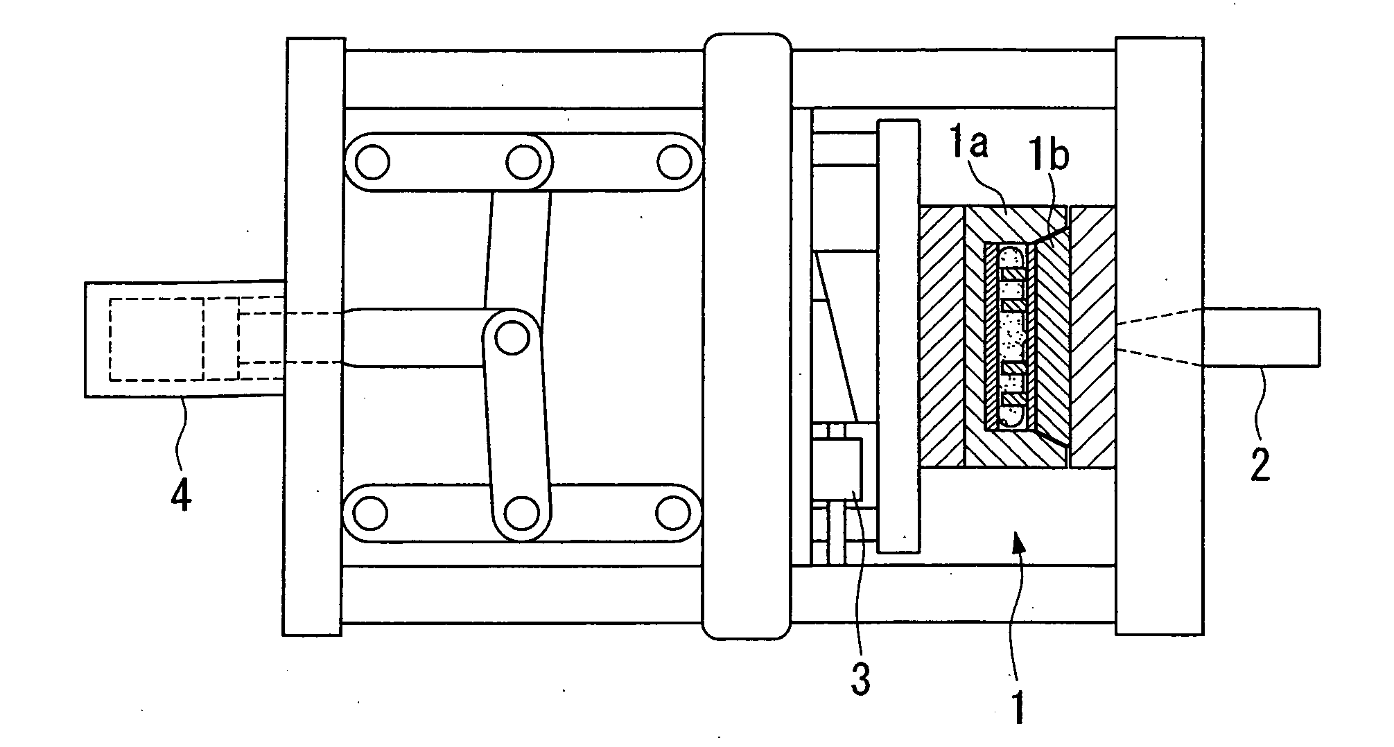
[0062] An example of the present invention is shown in FIG. 4.

[0063] In a fine channel substrate 8 (external diameter φ=140 mm, thickness t=2.0 mm) were formed 18 Y-shaped fine channels, each containing concave portions (width W=200 μm, depth (height) D=100 μm) corresponding with fine channels 9 for flowing fluids. 54 through holes (diameter φ=1.2 mm) that connected with the fine channels were formed as fluid inlet portions 10a, 10b or fluid discharge portions 11.

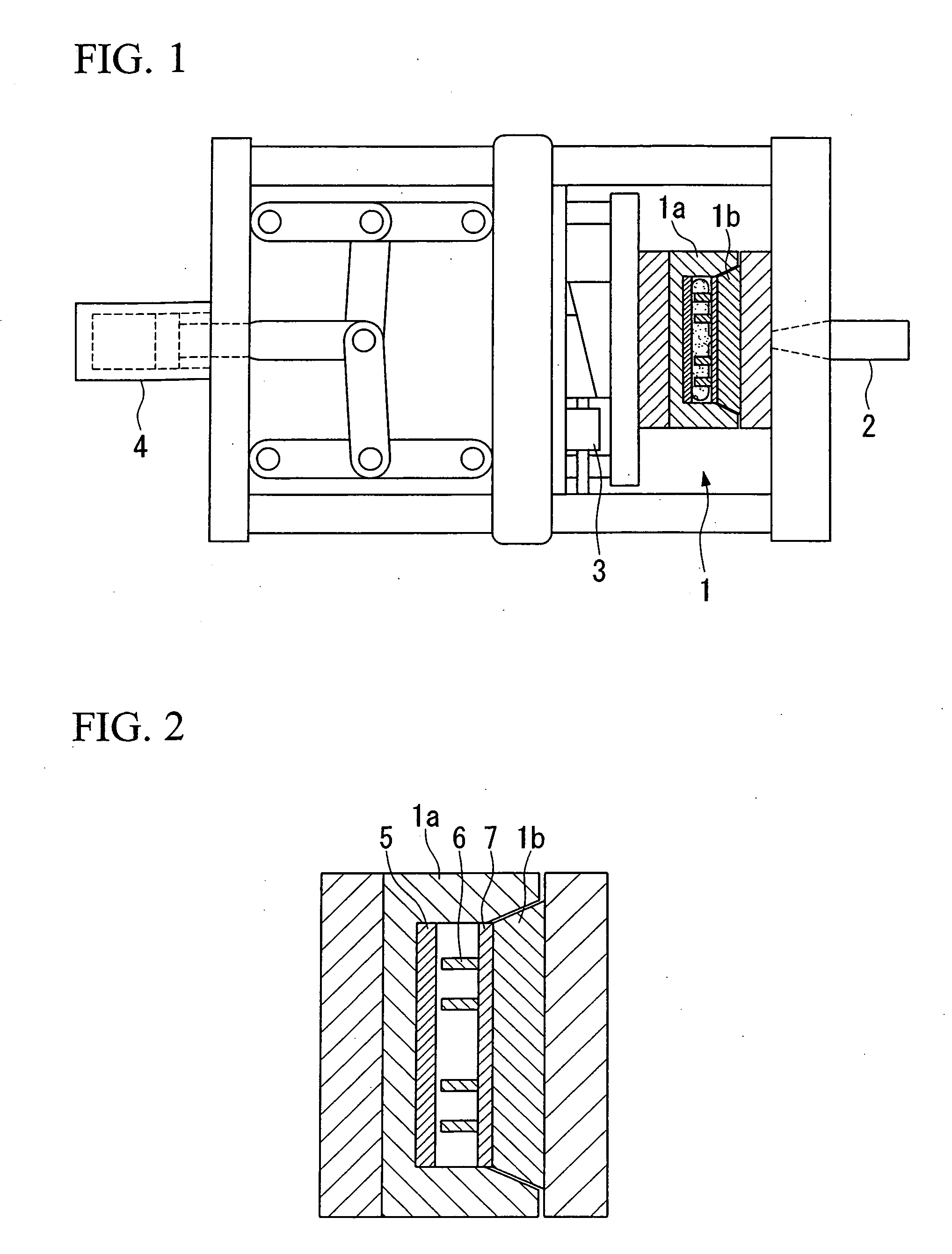
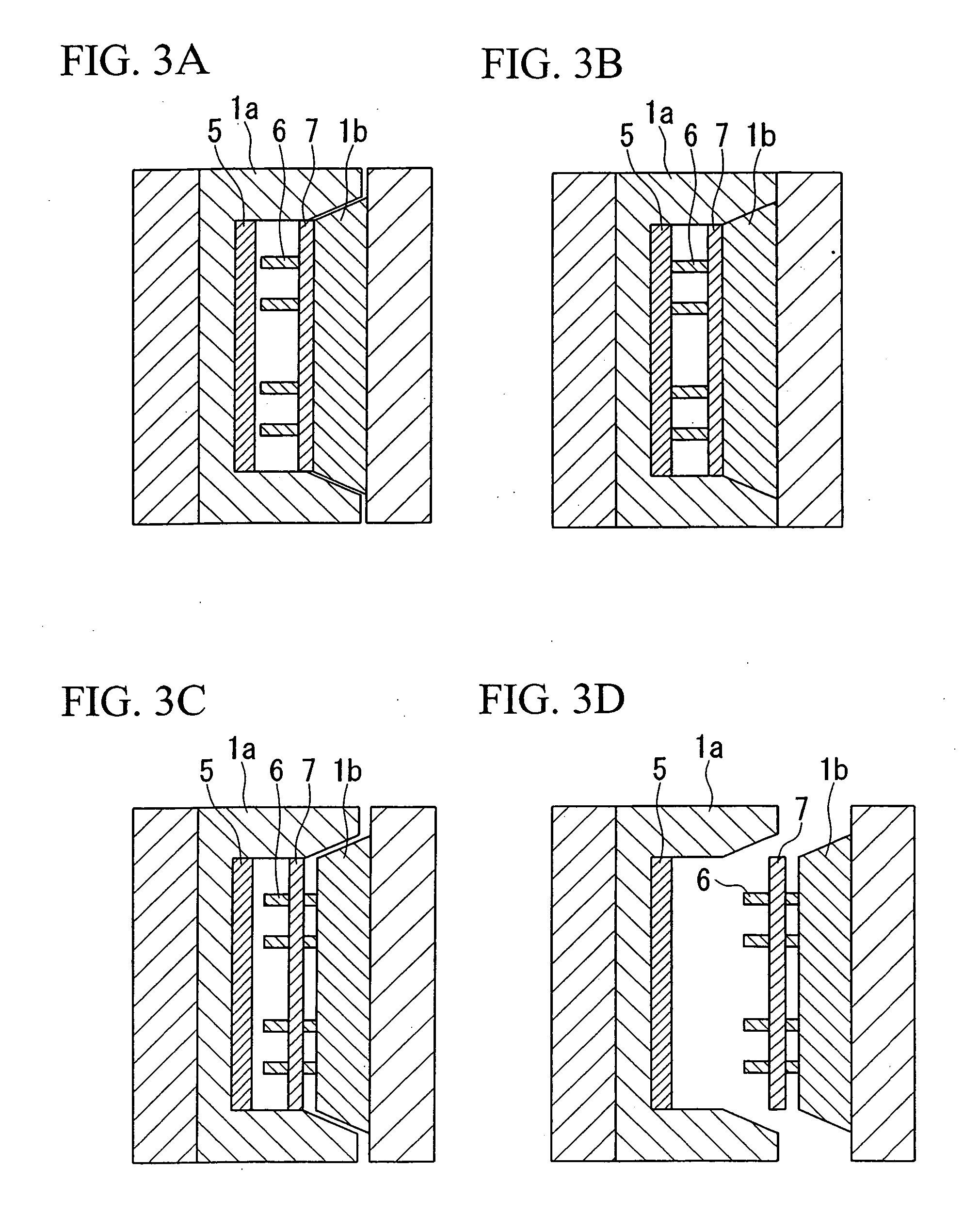
[0064] The mold used to form both the concave portions corresponding with the fine channels 9 and the through holes was as described below. A stamper 5 including convex portions corresponding with the fine channels 9 was mounted to the movable mold 1a of an injection molding device. The fixed mold 1b was equipped with pins 6 of external diameter φ=1.2 mm for forming the 54 through holes in positions corresponding with the fluid inlet portions 10a, 10b, and the fluid discharge portions 11. In addition, an ejector plate 7, ...


PUM

PropertyMeasurementUnit
Surface roughnessaaaaaaaaaa
Flow rateaaaaaaaaaa

Abstract

A fine channel device containing a fine channel substrate that includes a fine channel for channeling fluids, and through holes, wherein the fine channel and the through holes are interconnected via an interconnection portion, as well as a mold that is equipped with pins for forming the through holes in the fine channel substrate, wherein the positions of the pins and the number of pins can be altered as desired.

Description

BACKGROUND OF THE INVENTION [0001] 1. Field of the Invention [0002] The present invention relates to a fine channel device and a mold. [0003] Priority is claimed on Japanese Patent Application No. 2003-061640, filed Mar. 7, 2003, the content of which is incorporated herein by reference. [0004] 2. Description of Related Art [0005] In recent years, much attention has been focused on research using fine channel devices, wherein fine channels with a length of several cm, and a width and depth within a range from the sub-micron level to several hundreds of μm are formed on top of a square glass substrate with a side dimension of several cm, and these fine channel devices are then used for conducting chemical and physical operations such as chemical reactions, chemical syntheses, analysis, separation, and extraction (for example, see H. Hisamoto et al., Fast and high conversion phase-transfer synthesis exploiting the liquid-liquid interface formed in a microchannel chip, Chem. Commun., 20...

Claims


Application Information

Patent Timeline
IPC IPC(8): B01D17/00B29C33/00B01L3/00B29C45/26B29C45/56
CPCB01L3/502715B01L3/502746B01L2200/12B01L2300/0806B81C99/008B29C45/2673B29C45/561B29C2045/564B81B2203/058B29C45/2628
Inventor KAWAI, AKIRAHARA, KATSUYUKIKATAYAMA, KOJIFUTAMI, TORU
Owner TOSOH CORP
Features
  • R&D
  • Intellectual Property
  • Life Sciences
  • Materials
  • Tech Scout
  • Unparalleled Data Quality
  • Higher Quality Content
  • 60% Fewer Hallucinations
Learn More