Urea concentration identification device for urea solution

a technology of urea solution and identification device, which is applied in the direction of machines/engines, glassware laboratories, instruments, etc., can solve the problems of insufficient sensitivity of nox sensors used in this method, uneven concentration distribution locally in the tank, etc., and achieves improved precision, improved accuracy, and stable performance.

Active Publication Date: 2007-03-08
SAN-A
View PDF2 Cites 24 Cited by
  • Summary
  • Abstract
  • Description
  • Claims
  • Application Information

AI Technical Summary

Benefits of technology

[0016] According to the present invention, since a urea concentration is identified for urea solution stored in a tank, a concentration identification sensor unit is arranged inside the tank, and urea concentration identification with desirable precision can be stably performed without being affected by external environmental conditions.
[0017] Furthermore, according to the present invention, since a urea concentration is identified at an identification operation unit based on an output of a concentration detection circuit by applying a single-pulse voltage to a heating element of an indirectly-heated concentration detector to make the heating element generate heat, a urea concentration in urea solution can be identified correctly as well as promptly. Especially, if a urea concentration is identified using a concentration correspondence volta

Problems solved by technology

Urea solution, which is stored in a urea solution tank carried on an automobile, may have its concentration changed as time goes by, and furthermore, there may be raised unevenness in concentration distribution locally in the tank.
However, this method is employed to measure the effect of actual reduction of NOx, and cannot identify a urea concentration not only before spraying urea solution but also from the very beginning of spraying urea solution.
Moreover, NOx sensors used in this method are not sufficient in sensitivity for realizing spraying urea solution of a desired concentration.
However, since

Method used


Image

  • Urea concentration identification device for urea solution
  • Urea concentration identification device for urea solution
  • Urea concentration identification device for urea solution

Examples


Embodiment Construction

[0033] The present invention will further be described below concerning the best modes with reference to the accompanying drawings.

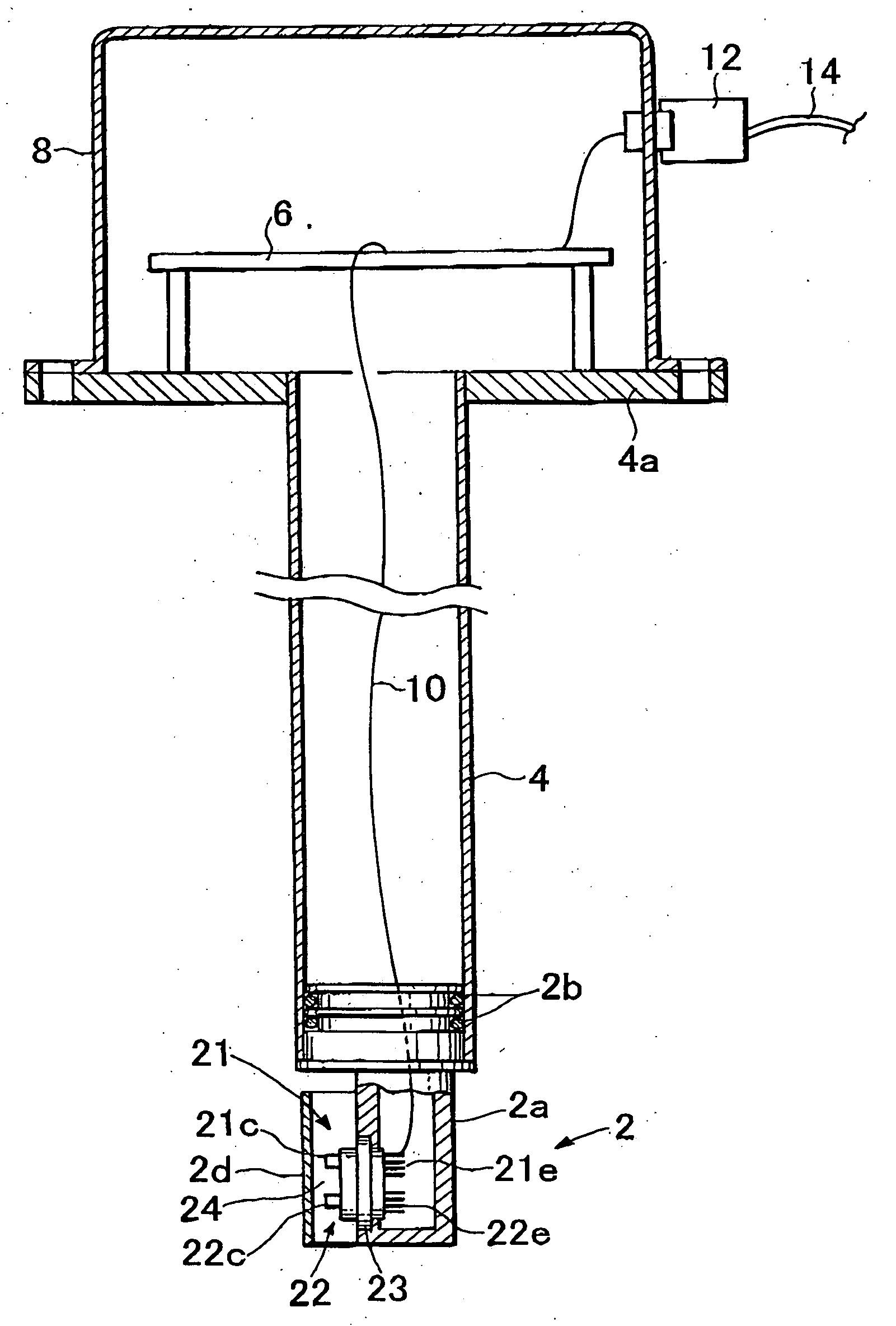
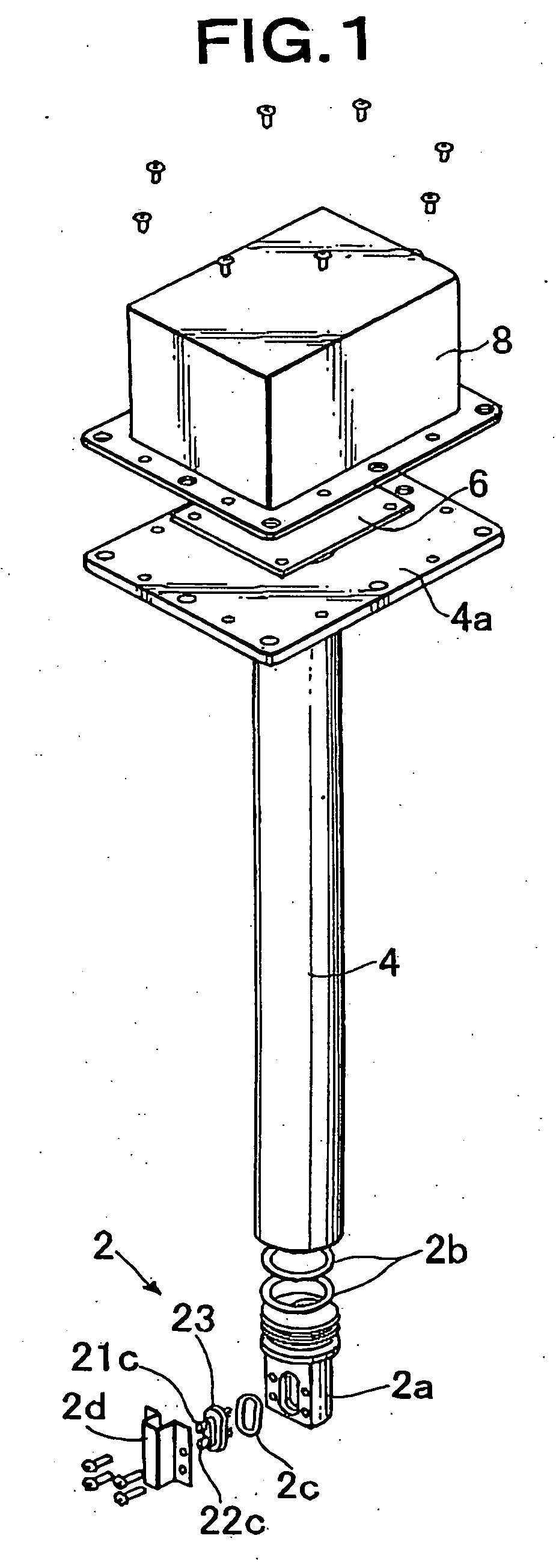
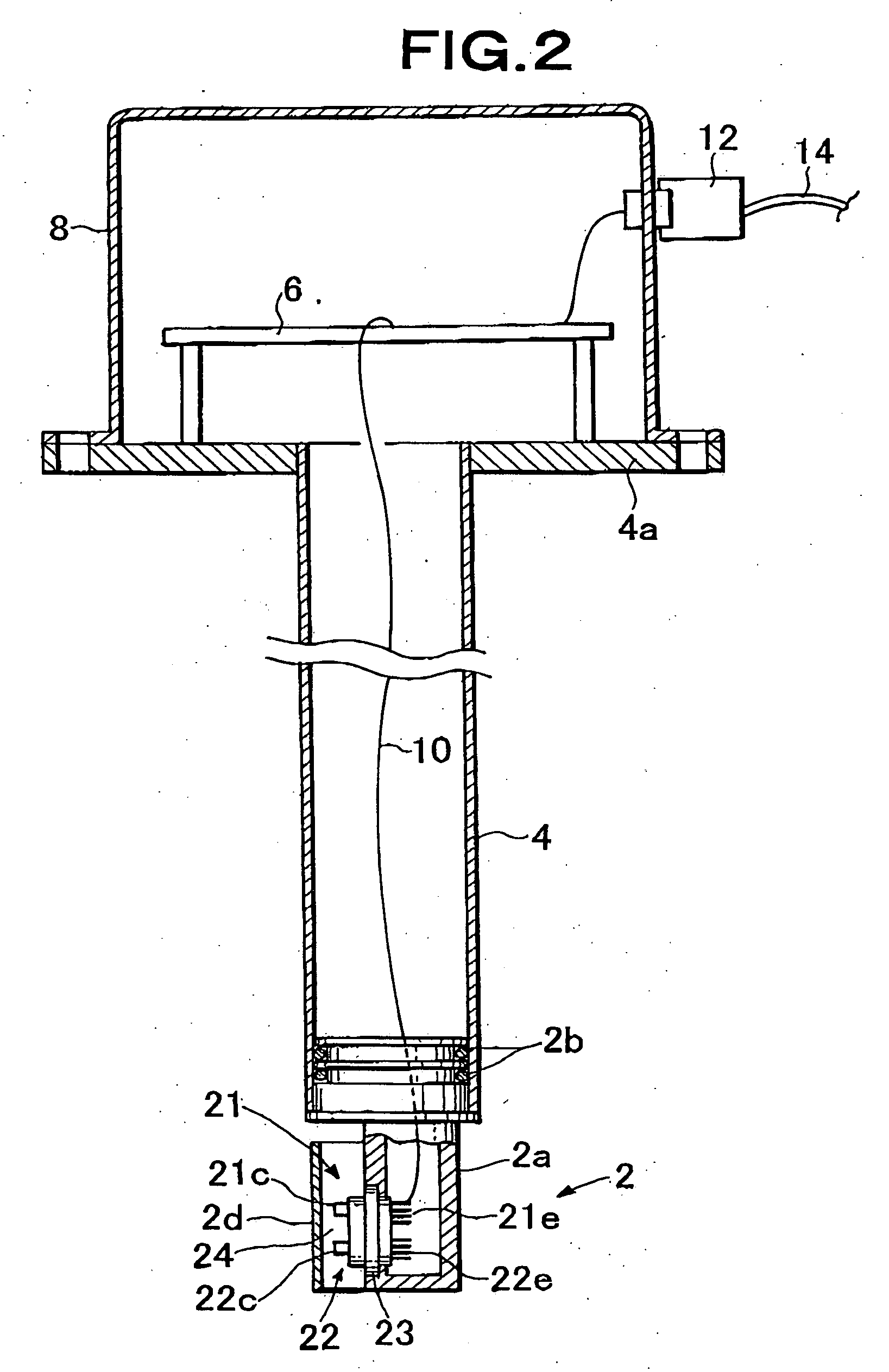
[0034]FIG. 1 shows an exploded perspective view of one embodiment of the urea concentration identification device according to the present invention, FIG. 2 shows a sectional view of the same, part of which is omitted, and FIG. 3 shows a view indicative of the state of mounting the same to a tank.

[0035] As shown in FIG. 3, a urea solution tank 100 for decomposing NOx, which constitutes an exhaust purification system carried on an automobile, etc., is provided with an opening 102 on the top thereof, and a urea concentration identification device 104 according to the present invention is mounted to the opening 102. To the tank 100, an inlet pipe 106 from which urea solution is let in and an outlet pipe 108 from which urea solution is taken out are fixed. The outlet pipe 108 is coupled to the tank 100 at a height located near the bottom thereof, and is co...


PUM


Abstract

A urea concentration identification device comprising a concentration identification sensor unit (2) and a support unit (4) attached at the bottom end thereof with this sensor unit and provided at the top end thereof with a mounting unit (4a) to a urea solution tank opening. The concentration identification sensor unit (2) has an indirectly-heated concentration detector and liquid temperature detector provided with metal fins (21c),(22c), respectively, for heat-exchanging with urea solution. The concentration identification sensor unit (2) is provided with a cover member (2d) that forms an opposite-ends-opened urea solution induction passage so as to surround the metal fins (21c), (22c). A single-pulse voltage is applied to the heating element of the indirectly-heated concentration detector to heat it, and a urea concentration is identified at an identification operation unit based on an output from a concentration detection circuit including the temperature sensing element of the indirectly-heated concentration detector and the liquid temperature detector.

Description

TECHNICAL FIELD [0001] The present invention relates to a device for identifying a urea concentration in urea solution which is to be sprayed to exhaust purification catalyst so as to decompose nitrogen oxides (NOx) in a system to purify exhaust discharged from an internal-combustion engine of an automobile, etc. BACKGROUND ART [0002] In an internal-combustion engine of an automobile, fossil fuel such as gasoline or gas oil is burnt. Exhaust that is generated along with the combustion includes, together with water and carbon dioxide, environmental pollutants such as unburned carbon monoxide (CO) and carbon hydride (HC), sulfur oxides (SOx), and nitrogen oxides (NOx). Recently, especially for environmental protection and to prevent living environment from being polluted, there are suggested various countermeasures to purify exhaust from an automobile. [0003] As one countermeasure, there is known the use of an exhaust purification catalyst device. According to this device, three way c...

Claims


Application Information

Patent Timeline
IPC IPC(8): G01N33/00G01N25/00F01N3/08G01N25/18
CPCF01N2610/148G01N25/18F01N3/2066F01N11/00Y10T436/171538F01N2610/10F01N2900/1818Y02T10/47F01N2610/02Y02T10/40
Inventor INOUE, SHINICHIKUBOTA, AKIKOTAKAHATA, TAKAYUKI
Owner SAN-A
Why Eureka
Try Eureka