Magnetic tape cartridge reel

a technology of magnetic tape and cartridge reel, which is applied in the field of magnetic tape cartridge reel, can solve the problems of easy damage to the edge affecting the rolled posture of the magnetic tape, and the width of the convex 33/b> (a part of the contacting magnetic tape) between the adjoining concave to be decreased, so as to achieve enhanced force, strong tensile strength of the flange, and simple structure

Active Publication Date: 2006-04-25
FUJIFILM HLDG CORP +1
View PDF3 Cites 4 Cited by
  • Summary
  • Abstract
  • Description
  • Claims
  • Application Information

AI Technical Summary

Benefits of technology

[0022]According to this composition, when the magnetic tape is subjected to an impact shock, the portion between the cartridge case and the flanges absorbs the shock. Also, since the portion is between the cartridge case and the flange, there is generated a space, which is thickness of the portion. Because of the space, flanges can bend, so further the shock given to the tape is absorbed. Further, because a centrifugal force is added and the tensile strength of the flanges becomes strong, when the flange rotates, the flanges can have an enhanced force for maintain their plain shape.

Problems solved by technology

Also, in the above magnetic tape cartridge, the magnetic tape is wound on the reel involving in air so called an involved-in air badly affects the rolled posture of the magnetic tape.
But there is a problem that enlarging the thickness in the radial direction of the groove 15a to improve the functionality of releasing the involved-in air, causes the width of a convex 33 (a part of contacting magnetic tape) between the adjoining concaves to be decreased.
This is, because the flange 15 forming the reel has high rigidity, in the case when the tape edge contacts with the flange when the magnetic tape is wound on the reel, the edge of the magnetic tape is damaged easily.
Accordingly, there easily occurs edge damages such as bending or collapsing.
In this case, there is a possibility that some of servomechanism or some of running / recording position detecting systems can not detect the tape edge and the tape can not run.

Method used


Image

  • Magnetic tape cartridge reel
  • Magnetic tape cartridge reel
  • Magnetic tape cartridge reel

Examples


first embodiment

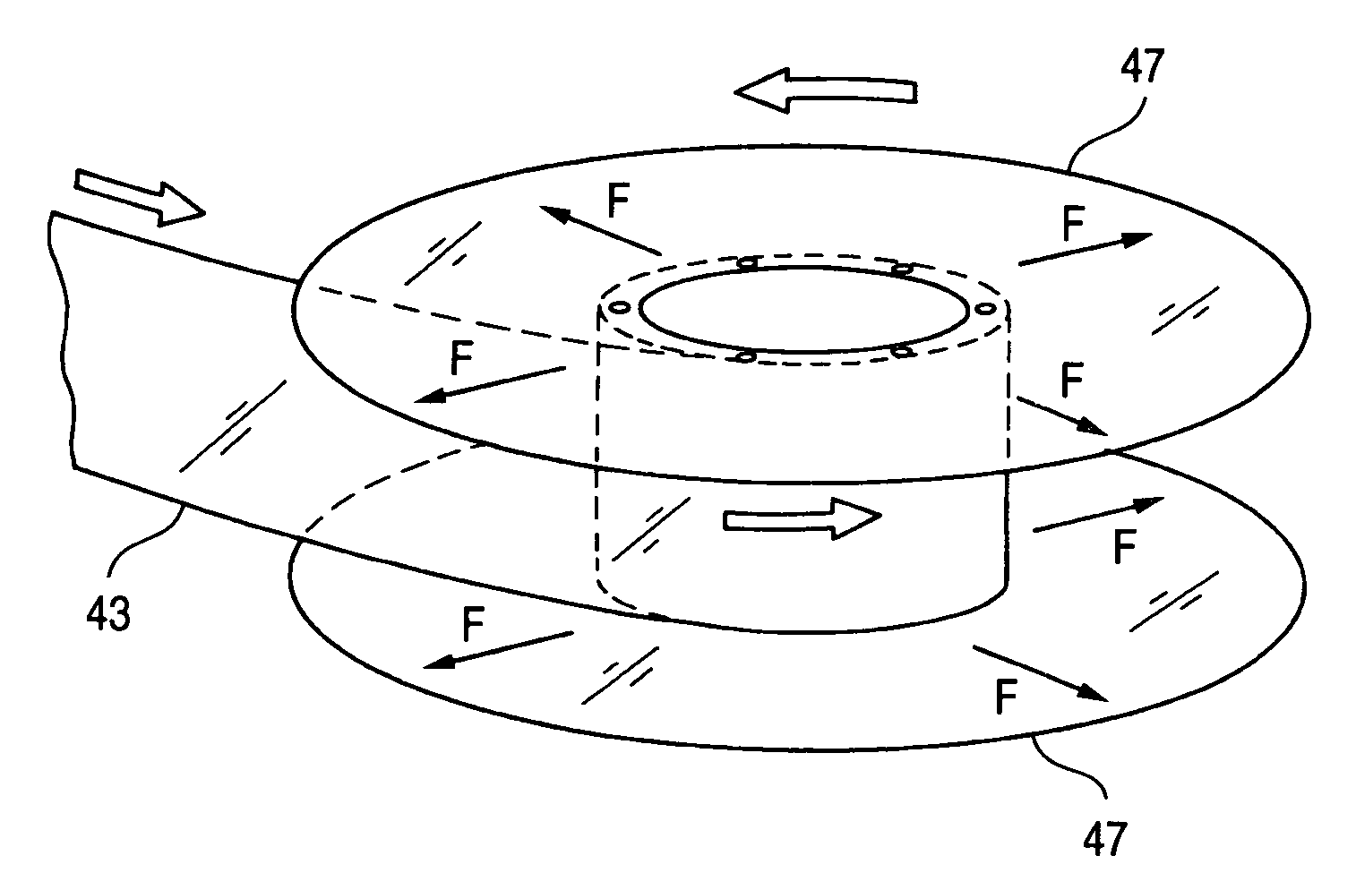
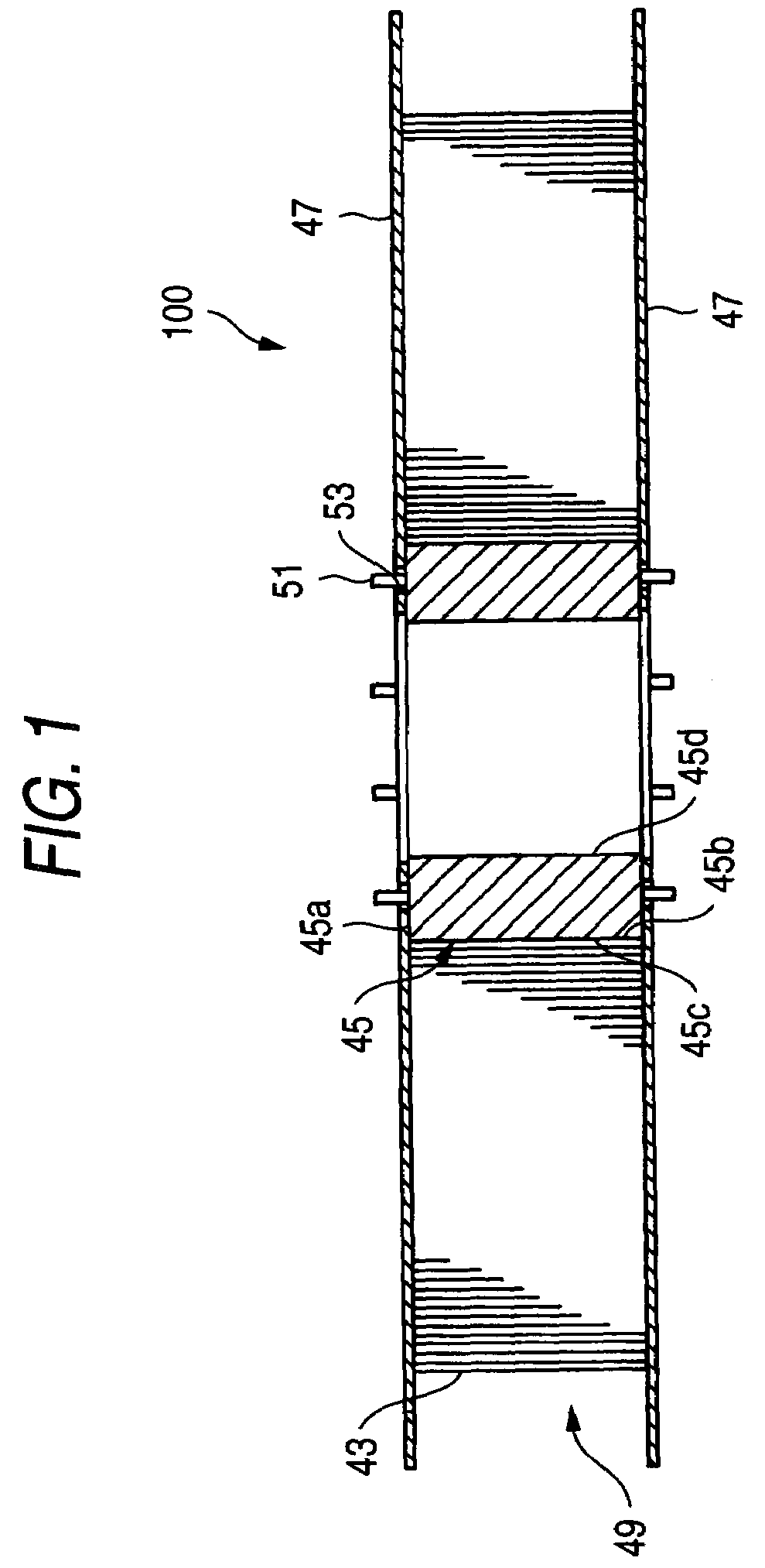
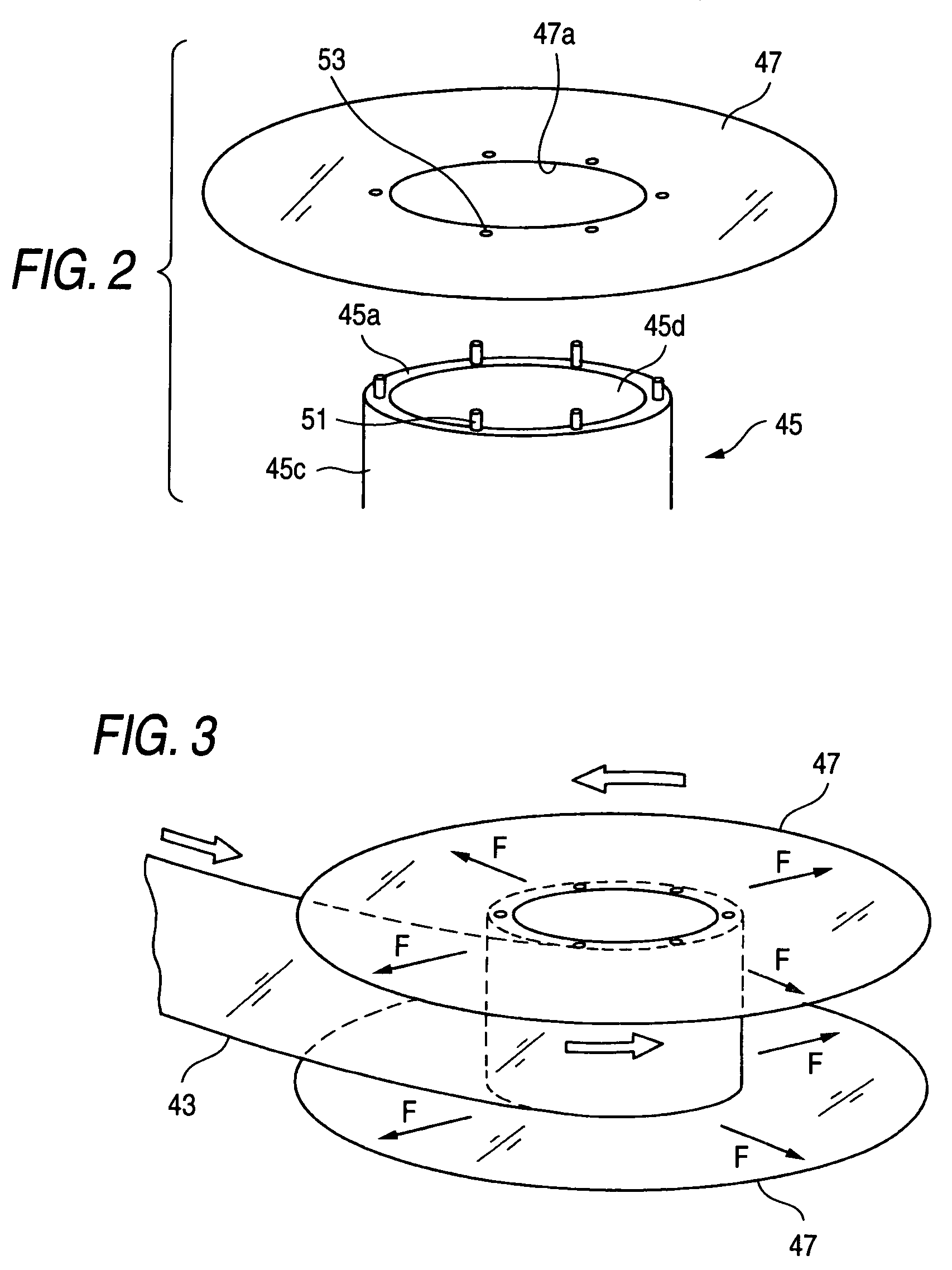
[0036]FIG. 1 is a longitudinal section of a magnetic tape cartridge tape reel according to the present invention. FIG. 2 is an exploded perspective view of a hub and a flange shown in FIG. 1. FIG. 3 is an operational view of the magnetic tape cartridge reel shown in FIG. 1.

[0037]As shown in FIG. 1, a magnetic tape cartridge reel 100 (Hereafter, only described as a reel) comprises; A hub 45 where a magnetic tape 43 is wound around the perimeter, a pair of flanges 47, 47 attached on the both end-side surfaces 45a, 45b of the axial direction of the hub 45. In this embodiment, the hub 45 is formed cylindrical-shape as shown in FIG. 2, the both end-side surfaces of the axial direction open and are ring-shape in plane.

[0038]Each flange 47 is made of flexible material and is separately formed from the hub 45. The diameter of the flange 47 is the same or larger than that of the tape wound body 49 (which magnetic tape 43 is wound). Also, the flange 47 is formed cylindrical-shape, inner hole ...

second embodiment

[0046]Next, magnetic tape cartridge of the present invention is explained.

[0047]FIG. 4 is a longitudinal section of the second embodiment of the magnetic tape cartridge reel.

[0048]The reel 200 of the embodiment is, as well as the above-mentioned embodiment reel 100, a flange 63 and a hub 67 are formed separately, and the flange 63 consists of a flexible material. In the inner hole 67a of the hub 67, the cylinder 69 on which one end has a brim 69a is inserted.

[0049]In the cylinder 69, the diameter of the brim 69a is formed as same as that of hub 67. On the peripheral 69b of the cylinder 69, there are projections 71. The projections 71 fit in the concave 73 which is formed on the inner hole 67a of the hub 67. Because the cylinder 69 inserted in the inner hole 63a of the hole 63 further fits in the inner hole 67a of the hub 67, the peripheral of the inner hole 63a is sandwiched between the brim 69a and the end side 67b of the hub 67, and the flange 63 is fixed.

[0050]In this embodiment,...

third embodiment

[0052]Next, the magnetic tape cartridge reel of the present invention is explained.

[0053]FIG. 5 is an appearance perspective view of the magnetic tape cartridge reel of this embodiment.

[0054]The reel 300 of this embodiment is, a ring-shape portion 83 comprises a single unit having a substantially similar to the perimeter of the flange 47 is formed on the flange 47 positioned between a perimeter of the flange 47 and an aperture of the flange 47.

[0055]The ring-shape portion 83 may have a shock proof and shock absorbing function. As the material of this ring-shape portion 83, for example, foaming material which has shock proof property and shock absorbing property is preferable. And it is desirable that the specific gravity of the material is heavier than the film which composes the flanges 47. In this embodiment, this ring-shape portion 83 is attached on the most out side peripheral of the flange 47. Also, this ring-shape portion 83 maybe formed in applying liquid and stiffening it.

[0...


PUM

PropertyMeasurementUnit
thicknessaaaaaaaaaa
thicknessaaaaaaaaaa
thicknessaaaaaaaaaa

Abstract

A magnetic tape cartridge reel includes a hub having a first end and a second end configured to receive a magnetic tape to be wound thereon and at least one flange which is attached to at least one of the first end and the second end of the hub, wherein the at least one flange is formed separately from the hub and is made of a flexible material.

Description

BACKGROUND OF THE INVENTION[0001]1. Field of the Invention[0002]The present invention relates to a magnetic tape cartridge reel on which a magnetic tape is wound and stored within a magnetic tape cartridge.[0003]2. Description of the Related Art[0004]Conventionally, as a magnetic tape cartridge which has been used as a recording medium for use in external memory such a computer, there is known a magnetic tape cartridge of a type in which a single reel with a magnetic tape is wound thereon. The magnetic tape cartridge is used for storing data of a computer.[0005]As shown in FIG. 6, this type of magnetic tape cartridge 1 is composed in such a manner that a reel 7 consists of a lower flange and an upper flange welded by ultra sonic welding is rotatably stored into a cartridge case 11 composed of an upper case 11a and a lower case 11b fastened together with screws.[0006]The lower flange 3 is made of synthetic resin and is an integral body composed of a cylindrical-shape hub 13 on the ou...

Claims


Application Information

Patent Timeline
Patent Type & Authority Patents(United States)
IPC IPC(8): B65H75/12G11B23/037B65H75/14
CPCB65H75/14B65H2701/5152B65H2701/514
Inventor SHIGA, HIDEAKI
Owner FUJIFILM HLDG CORP
Why Eureka
Try Eureka