

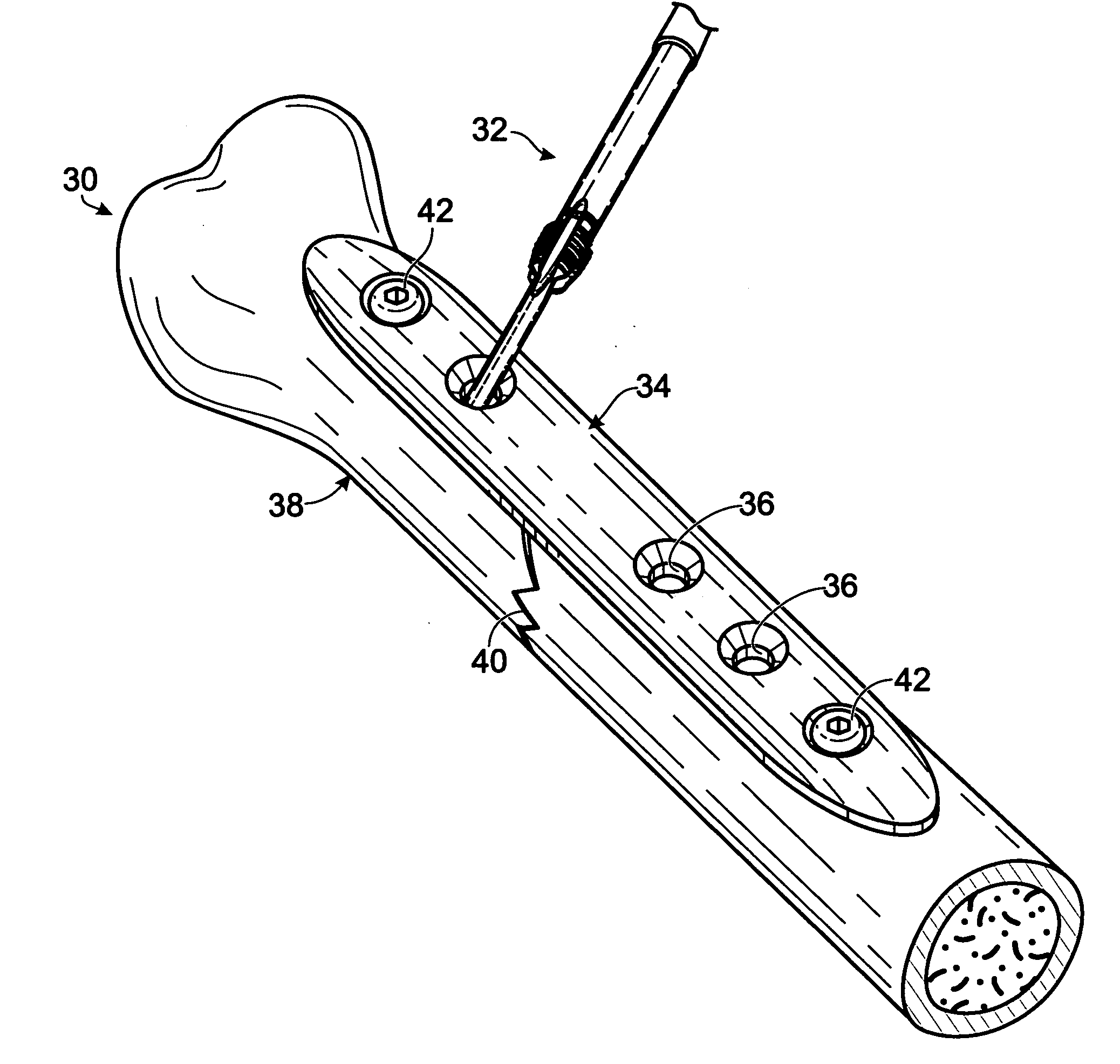
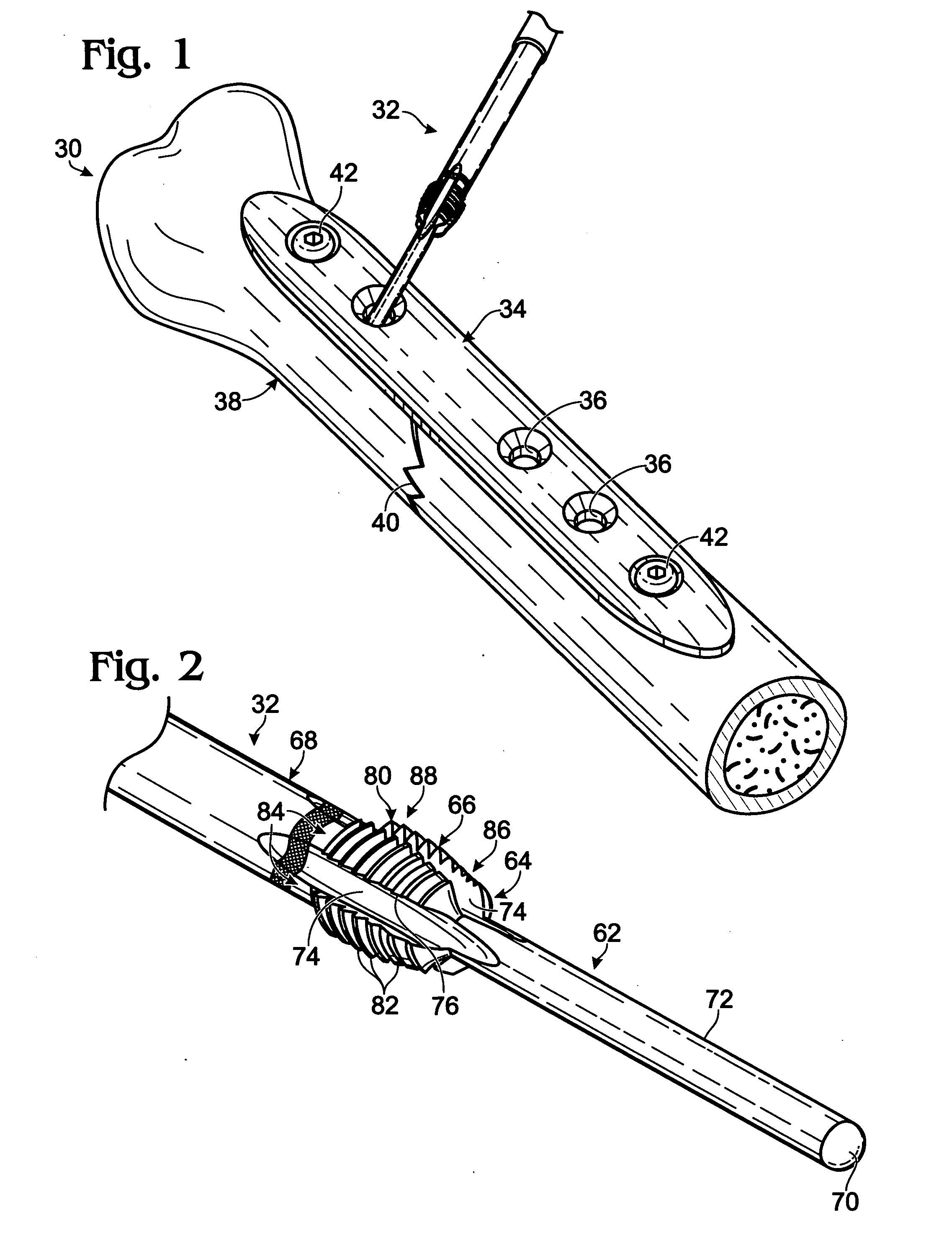
Bone plates with intraoperatively tapped apertures
- Summary
- Abstract
- Description
- Claims
- Application Information
AI Technical Summary
Benefits of technology
Problems solved by technology
Method used
Image

Examples
example 1
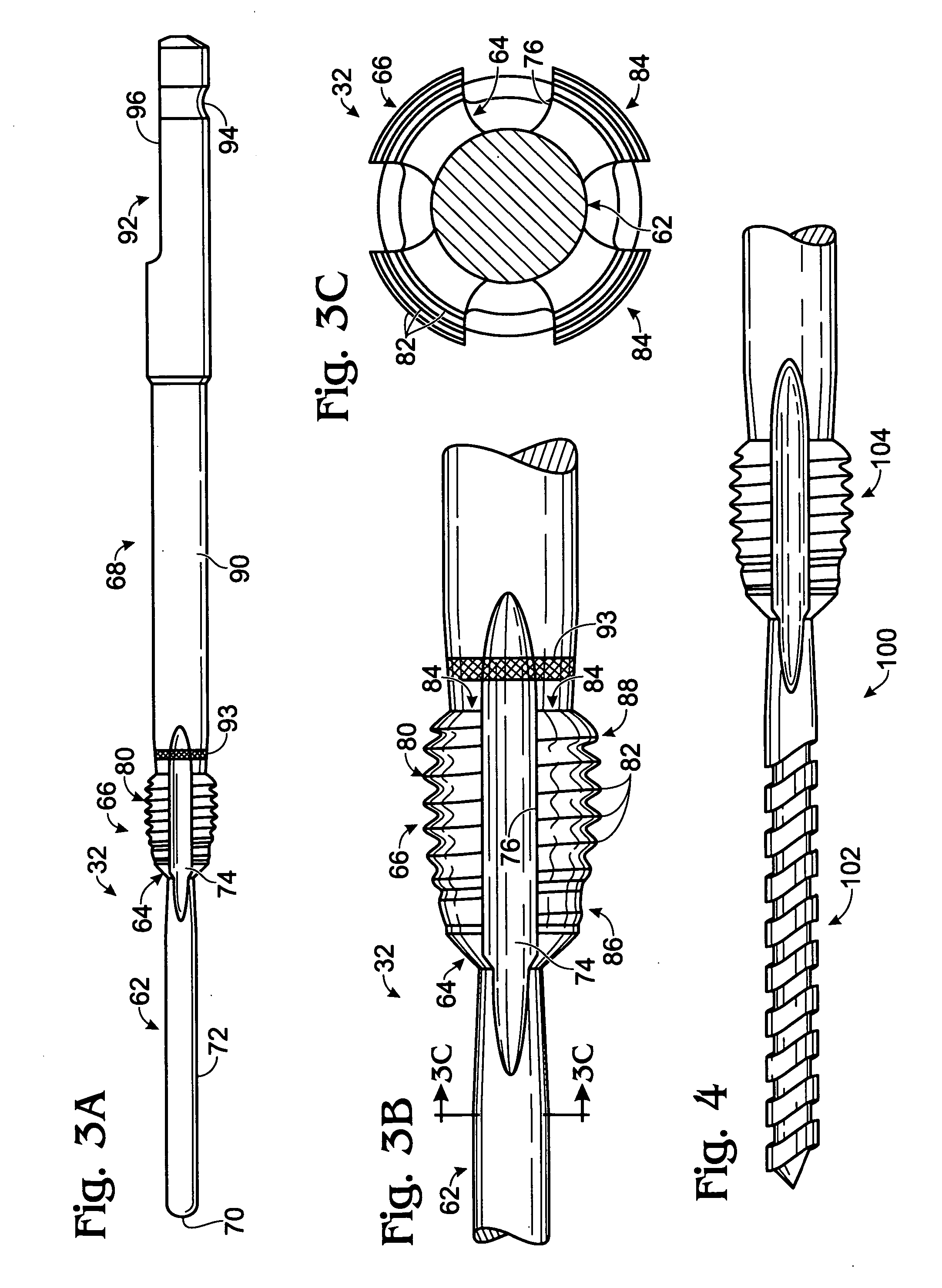
Roll Tap Device
[0102] This example describes an exemplary tap device 260 that creates a thread via roll tapping; see FIG. 14.
[0103] Tap device 260 may include a leading portion 262 joined to a trailing portion 264. The leading portion may include a tap portion 266 joined to a tip portion 268. Accordingly, the leading portion may be configured as an entry portion that enters and / or passes through the bone plate into bone. The tap portion may be configured to form a thread in the aperture of a bone plate mostly by deforming rather than cutting the bone plate (i.e., by “roll tapping”). Accordingly, tap portion 266 may have a thread 270 that lacks cutting flutes (e.g., compare tap device 260 with the tap device shown in FIGS. 3A-3C). Tip portion 268 may be structured as a drill bit, as shown here, or may lack cutting structure.
[0104] Trailing portion 264 may be formed as a proximal extension or external portion extending proximally from the leading portion. Most or all of the trailin...
example 2
Wire-Guided Intraoperative Tapping
[0107] This example describes an exemplary approach to guiding a tap device using a wire placed in bone; see FIGS. 15 and 16.
[0108]FIG. 15 shows a bone plate 280 disposed on a bone 282, with a guide wire 284 extending through a tappable aperture 286 of the bone plate and also through the bone. The guide wire may define a path and thus angle at which the aperture is tapped. In some examples, the guide wire may extend into but not through the bone.
[0109]FIG. 16 shows bone plate 280, bone 282, and wire 284 with roll tap device 260 (also see FIG. 14) received on the wire and advanced into engagement with the bone plate. The roll tap device may be advanced by rotation such that the aperture is tapped by the tapping portion of the roll tap device, indicated at 288. Any other partially or completely cannulated tap device may be used in place of the roll tap device shown here, such as a cutting tap device (e.g., see FIGS. 1-3).
example 3
Exemplary Bone Plates with Tappable Apertures
[0110] This example describes exemplary bone plates with tappable apertures that flare toward the inner surface of the bone plates; see FIGS. 17-19.
[0111]FIG. 17 shows an exemplary bone plate 310 having a tappable aperture 312 that flares. The aperture may have a tappable region 314 configured to be tapped and a counterbore 316 disposed outward of the tappable region (or the counterbore may be absent from the aperture). The tappable region may include opposingly flared regions (that is, flaring away from one another). The flared regions may flare at about the same angle relative to orthogonal from the inner surface of the bone plate, or at different angles. Exemplary angles of flaring may be about 5 to 20 degrees or about 10 degrees from orthogonal, among others. In the present illustration, the tappable region flares toward an inner surface 318 of the bone plate, indicated at 320, and also flares toward an outer surface 322 of the bone...
PUM
 Abstract
Description
Claims
Application Information