Apparatus and methods for providing a flow of a heat transfer fluid in a microenvironment

a technology of heat transfer fluid and apparatus, which is applied in the field of apparatus and methods for handling heat transfer fluid in a microenvironment, can solve the problems of wearer discomfort, potentially life-threatening injury, and reduced performan

Inactive Publication Date: 2007-03-08
FORTHRIGHT ENG PLLC
View PDF35 Cites 9 Cited by
  • Summary
  • Abstract
  • Description
  • Claims
  • Application Information

AI Technical Summary

Problems solved by technology

Such gear may tend to trap heat (including body heat) and humidity (e.g., from perspiration) within the gear.
The trapped heat and humidity may cause the wearer discomfort.
Under stren

Method used


Image

  • Apparatus and methods for providing a flow of a heat transfer fluid in a microenvironment
  • Apparatus and methods for providing a flow of a heat transfer fluid in a microenvironment
  • Apparatus and methods for providing a flow of a heat transfer fluid in a microenvironment

Examples


Embodiment Construction

[0012] The present invention now will be described more fully hereinafter with reference to the accompanying drawings, in which illustrative embodiments of the invention are shown. In the drawings, the relative sizes of regions or features may be exaggerated for clarity. This invention may, however, be embodied in many different forms and should not be construed as limited to the embodiments set forth herein; rather, these embodiments are provided so that this disclosure will be thorough and complete, and will fully convey the scope of the invention to those skilled in the art.

[0013] It will be understood that when an element is referred to as being “coupled” or “connected” to another element, it can be directly coupled or connected to the other element or intervening elements may also be present. In contrast, when an element is referred to as being “directly coupled” or “directly connected” to another element, there are no intervening elements present. Like numbers refer to like e...


PUM


Abstract

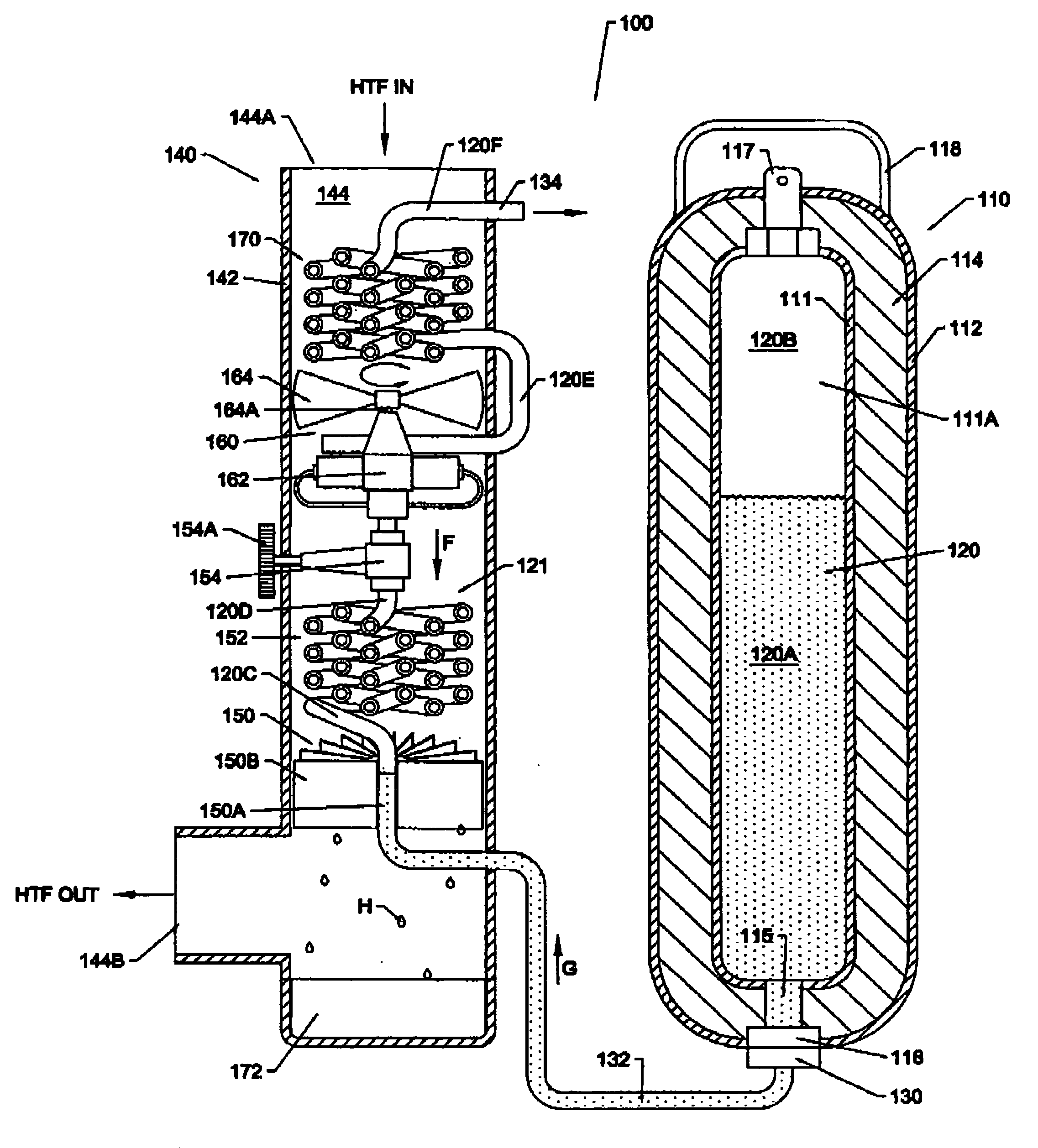
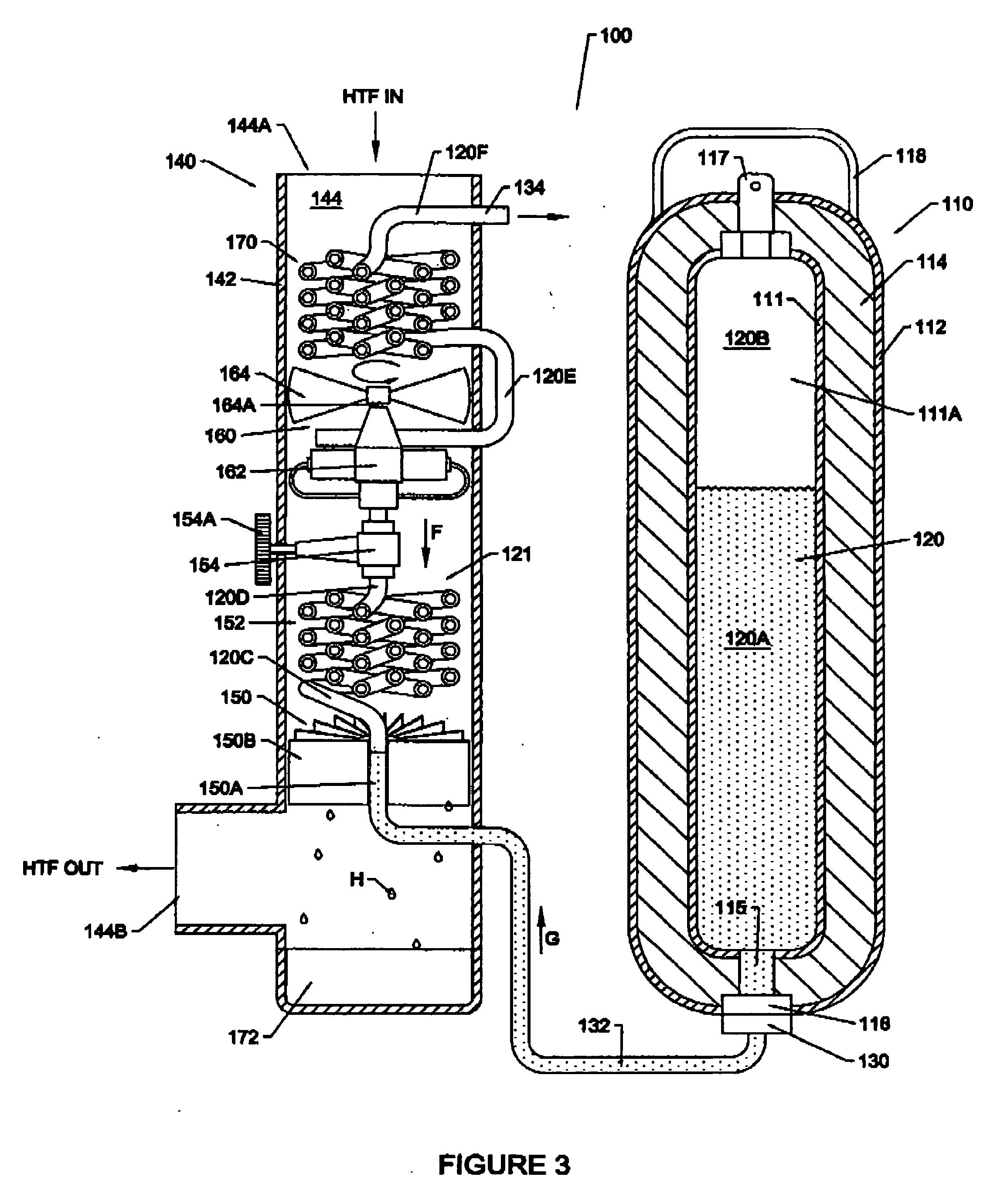
A microenvironment system for use with a heat transfer fluid includes a microenvironment structure and a fluid handling apparatus. The microenvironment structure defines a flow passage to receive a flow of the heat transfer fluid therethrough. The fluid handling apparatus is adapted to provide a flow of the heat transfer fluid through the flow passage. The fluid handling apparatus includes a gas driven pump and a supply of a phase change material (PCM). The gas driven pump is operable to force the flow of the heat transfer fluid through the flow passage. The supply of the PCM is convertible from a solid and/or liquid phase to a gas phase to provide a pressurized drive gas. The fluid handling apparatus is configured to drive the gas driven pump using the pressurized drive gas from the supply of the PCM.

Description

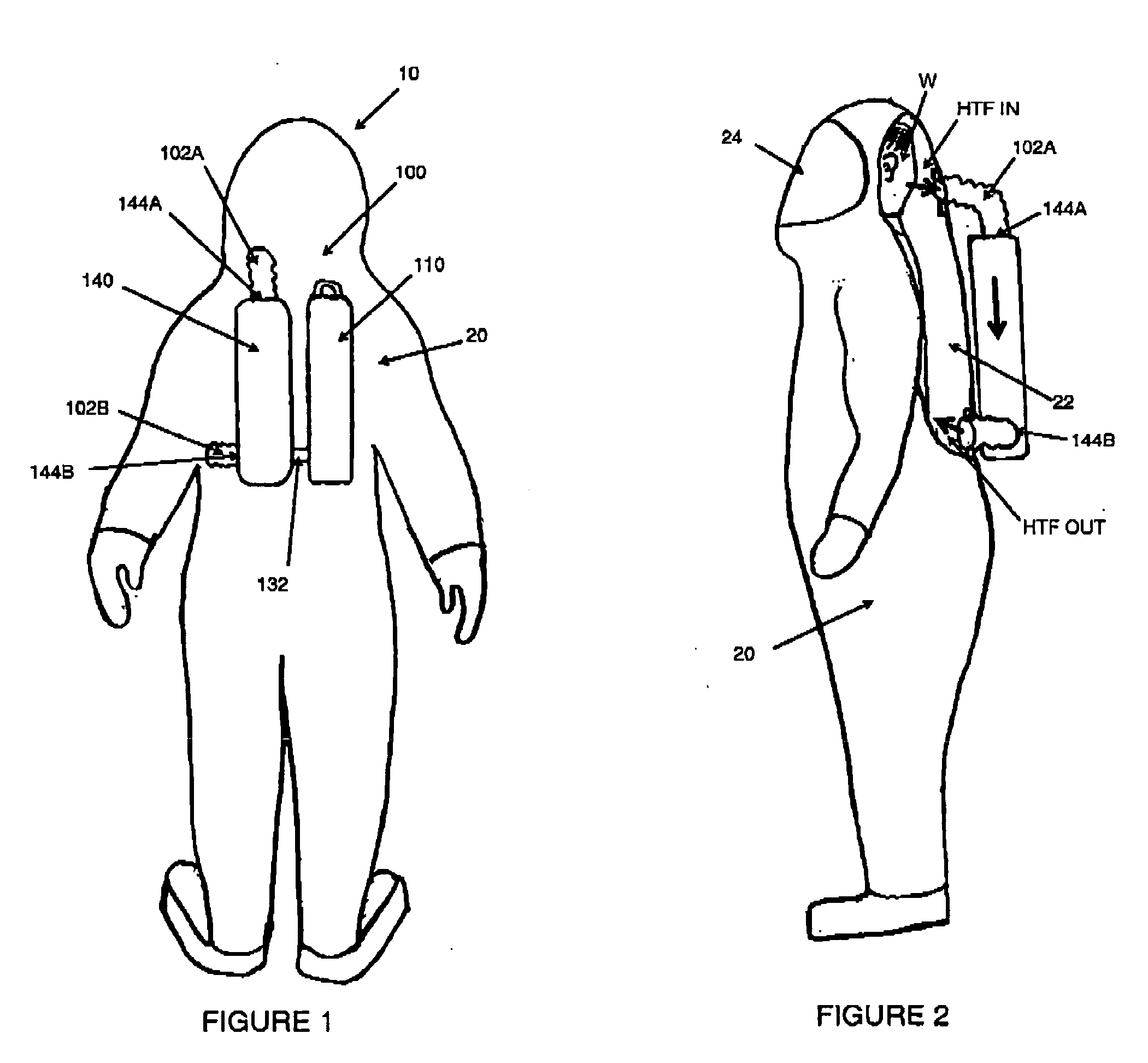
FIELD OF THE INVENTION [0001] The present invention relates to apparatus and methods for handling a heat transfer fluid in a microenvironment. BACKGROUND OF THE INVENTION [0002] It is often desirable or necessary to provide supplemental cooling to microenvironments or microclimates such as personal microenvironments. A personal microenvironment is an environment that exists in close proximity to an individual and moves with the individual as the individual moves. Examples of personal microenvironments include hazardous material (hazmat) suits, chemical / biological personal protective equipment, body armor, bombproof suits, turnout gear (e.g., fireman's gear), other protective gear worn by emergency responders and the like, etc. Such gear may tend to trap heat (including body heat) and humidity (e.g., from perspiration) within the gear. The trapped heat and humidity may cause the wearer discomfort. Under strenuous conditions and / or when there is a high ambient temperature, the wearer ...

Claims


Application Information

Patent Timeline
IPC IPC(8): A61F7/00F25D23/12
CPCA62B17/005F25D2400/26F25D3/107
Inventor WORM, STEVE L.
Owner FORTHRIGHT ENG PLLC
Why Eureka
Try Eureka