Buckling restrained braces and damping steel structures

a technology of damping steel structure and restraint braces, which is applied in the direction of construction, building types, building components, etc., can solve the problems of inability to constrain the local buckling the adhesion-preventing film has still other problems, and the inability to absorb the expansion in the plate thickness direction of the steel-made center axial member

Inactive Publication Date: 2007-03-15
NIPPON STEEL CORP
View PDF7 Cites 20 Cited by
  • Summary
  • Abstract
  • Description
  • Claims
  • Application Information

AI Technical Summary

Problems solved by technology

When the adhesion-preventive film is too thin, the film does not tolerate the expansion in the plate thickness direction of the steel-made center axial member caused by its axial deformation; on the other hand, when the adhesion-preventive film is too thick, it is incapable of constraining local buckling of the steel-made center axial member.
Moreover the adhesion-preventive film has still other problems as mentioned below.
When the stiffness in the thickness direction of the adhesion-preventive film is too low, it is incapable of maintaining a predetermined thickness due to the concrete pressure during pouring concrete; moreover, when the stiffness in the thickness direction thereof is too high, it cannot absorb the expansion in the plate thickness direction of the steel-made center axial member caused by the influence of Poisson's ratio at the time of plasticization, namely, plastic deformation of the steel-made center axial member.
When a plain steel (yield stress σy=235 N / mm2) is used for the steel-made center axial member of a buckling restrained brace, there arises a problem that the buckling restrained brace cannot be made to function as a hysteresis damper against an earthquake of a small magnitude because the steel-made center axial member does not yield at the early stage against a ground motion acceleration (80 to 100 gal) of the earthquake.
When the steel-made center axial member is made to function as a hysteresis damper, both ends as well as the central portion of the member are plasticized (plastically deformed) due to yielding, and consequently fracture at joints between the buckling restrained brace and a steel structure including a column and a beam takes place.
In the process of producing a buckling-constraining concrete member of a buckling restrained brace reinforced with a steel material, when the ends of the reinforcing steel material of a buckling-constraining concrete member are open, there arise problems as mentioned below.
During pouring the concrete, the concrete flows out before its solidification, and pouring concrete becomes difficult; cracked concrete falls during the use of the buckling restrained brace.

Method used


Image

  • Buckling restrained braces and damping steel structures
  • Buckling restrained braces and damping steel structures
  • Buckling restrained braces and damping steel structures

Examples


example 1

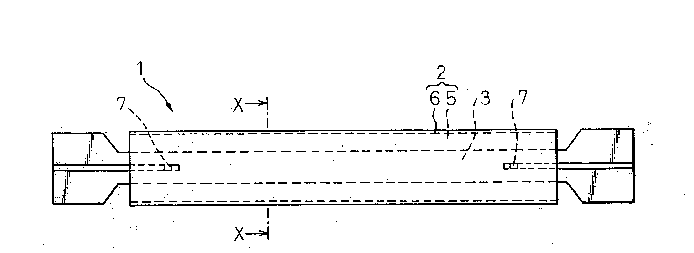
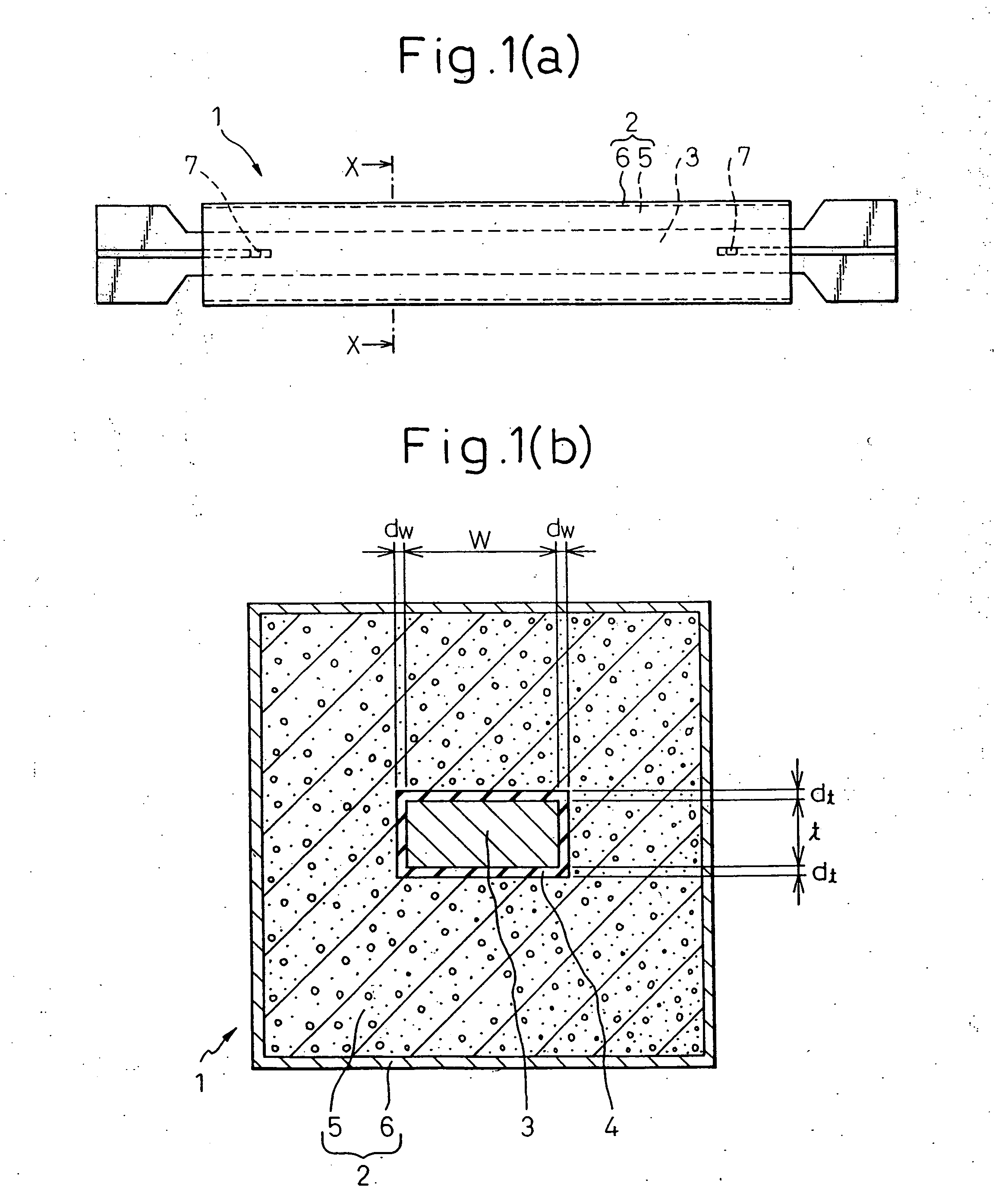
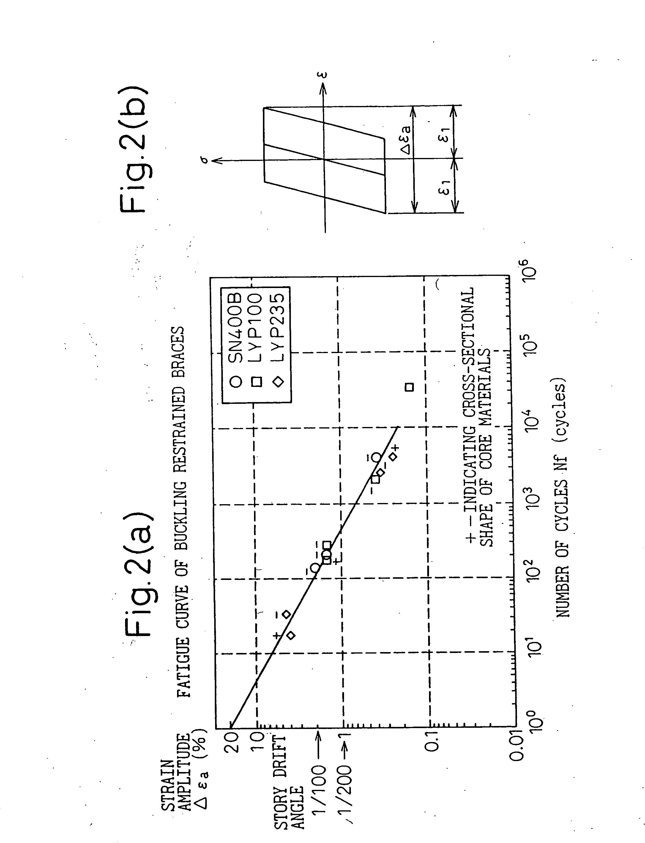
[0102] An adhesion-preventive film having a ratio (adhesion-preventive film ratio) of the film thickness to the plate thickness of a steel-made center axial member of at least 0.5 to 10% was provided between a buckling-constraining concrete member and the steel-made center axial member. When considering the pressure for placing concrete 5 in manufacturing a buckling-restraining brace 1, a lower limitation of a minimum thickness ratio dt(min) / t of the adhesion-preventive film 4 and a steel-made center axial member 3 is preferably about 1.2%. The adhesion-preventive film had a secant modulus in the thickness direction of at least 0.1 N / mm2 between a point having a compressive strain of 0% and a point having a compressive strain of 50%, and up to 21,000 N / mm2 between a point having a compressive strain of 50% and a point having a compressive strain of 75%. In the present example, a maximum axial strain amplitude Δεa of 4% was applied to a buckling restrained brace having an adhesive-pr...

example 2

[0104] Buckling restrained braces and a damping steel structure were clamping jointed with high tensile bolts. As shown in FIGS. 16 (a) and 16 (b) and FIGS. 17 (a) and 17 (b), steel-made connecting plates 27 having a surface hardness (Vickers hardness) and a surface roughness (ten point average roughness) 1.3 times larger than the surface hardness and surface roughness of both ends 22, 23 of the steel-made center axial members were used. Alternatively, in the friction jointing with high tension bolts mentioned above, both ends 22, 23 of the steel-made center axial member and the steel made-connecting plates 27 forming one friction jointing face were joined by the following procedure: the ratio of a hardness of the frictional surface layer portion of one of the two steel materials to a hardness of the frictional surface layer portion of the other steel material is at least 2.5; the depth of the surface layer portion having a higher hardness is at least 0.2 mm; a plurality of triangul...


PUM


Abstract

The present invention relates to a buckling restrained brace capable of absorbing vibration energy produced by an earthquake, wind power and the like, in a building and a steel structure. The buckling restrained brace of the present invention is accomplished by a buckling restrained brace 1 wherein a steel-made center axial member 3 is passed through a buckling-constraining concrete member 2 reinforced with a steel member 6, and an adhesion-preventive film 4 is provided to the interface between the steel-made center axial member and buckling-constraining concrete 5, the adhesion-preventive film showing a secant modulus in the thickness direction of at least 0.1 N / mm2 between a point which shows a compressive strain of 0% and a point which shows a compressive strain of 50%, and up to 21,000 N / mm2 between a point which shows a compressive strain of 50% and a point which shows a compressive strain of 75%, and having a thickness dt in the plate thickness direction of the steel-made center axial member and a thickness dw in the plate width direction thereof from at least 0.5 to 10% of the plate thickness t and from at least 0.5 to 10% of the plate width w, respectively, and by the application of the buckling restrained brace to a damping steel structure.

Description

CROSS REFERENCE TO RELATED APPLICATION [0001] This application is a continuation-in-part application of Ser. No. 09 / 511,207 filed on Feb. 23, 2000.BACKGROUND OF THE INVENTION [0002] 1. Field of the Invention [0003] The present invention relates to buckling restrained braces used in buildings and steel structures and capable of absorbing vibration energy generated by an earthquake, wind power, etc. [0004] 2. Description of the Related Art [0005] Japanese Examined Utility Model (Kokoku) No. 4-19121 discloses a buckling-constraining brace member in which an adhesion-preventive film is provided between a center axial member and a concrete member. Japanese Unexamined Utility Model (Kokai) No. 5-3402 discloses a buckling-constraining brace member wherein a steel-made center axial member is passed through a steel-made buckling-constraining member, and an adhesion-preventive film is placed between the surface of the center axial member and the buckling-constraining member. Japanese Unexamin...

Claims


Application Information

Patent Timeline
Patent Type & Authority Applications(United States)
IPC IPC(8): E04H9/02
CPCE04H9/028E04H9/02E04H9/0237
Inventor TAKEUCHI, TORUNAKAMURA, HIROSHIKIMURA, ISAOHASEGAWA, HISAMISAEKI, EIICHIROWATANABE, ATSUSHI
Owner NIPPON STEEL CORP
Why Eureka
Try Eureka