Buckling-restrained brace

a technology of buckling and restraining braces, applied in the field of buckling, can solve the problems of bending, affecting the performance of the brace, and reaching its limits, and achieve the effect of improving performance and reducing friction

Active Publication Date: 2013-08-15
SEISMIC BRACING CO LLC
View PDF5 Cites 19 Cited by
  • Summary
  • Abstract
  • Description
  • Claims
  • Application Information

AI Technical Summary

Benefits of technology

[0019]The layer of discrete springs provide a space so that when pressure is applied to the ends of the first end and the second end of the core plate, the material of the core plate may be compressed and expand laterally without contacting the grout matrix. In this way, the core plate is allowed to absorb the force of lateral loads without compromising the grout layer or the casing tube. The disclosed technology uses this layer or series of “discrete springs” between the core and the concrete which are attached to the core plate and which stay in place after the concrete solidifies. Thus it is not a “gap” nor is it a “film”, but it defines a space surrounding the core plate filled with discrete deformable material.
[0021]The technology operates so that when the core plate smashes (expands) and buckles, the discrete spring layer gives way, permitting the swelling of the core plate. The discrete spring layer also defines the size of the gap between the core plate and the inside of the concrete. Corrugated metal would be useful if the concrete is placed in the BRB when it is in a vertical orientation, as the pressure of the liquid concrete near the bottom end of a full BRB can be quite significant and in that orientation the discrete springs layer need to withstand that pressure or else they would collapse and then the concrete would be tight to the core plate, which is not good as explained in this document. If the brace is oriented generally horizontally when the liquid concrete is applied, the pressure from the liquid concrete would be minimal. The BRB could be tilted up a little during placement of the concrete, and thus the pressures due to the depth of the liquid above the bottom would be minimal. In such a horizontal pouring ordinary cardboard or corrugated plastic could be used as the “discrete spring” layer. The use of a layer of cardboard as the discrete spring layer also has significant economical advantages. Obviously, it cost less than UHMW, removable separators, ice & water shield and steel sheets. These systems (UHMW, removable separators, ice & water shield and steel sheets) also require mechanical fastening and sealing to keep them in place during concrete placement and to not let the concrete infiltrate between them and the core plate. Cardboard is easier to fabricate and easier to install, as it can be coated with adhesive and placed on the core plate, and then the concrete is poured / placed around it. The precision of the fit the cardboard around the core plate is not as critical, which increases permissible tolerances, making fabrication even easier. Also, the cardboard does not need to completely cover the core plate as long as it is sufficiently covered to accommodate the swelling of the core plate, thus requiring less material and fabrication time. For instance, cardboard could cover only one side of the core plate, and still provide the exact spacing required. Another major advantage of corrugated material verses some of the other technologies is that it can be fit to core plates with round cross sectional shapes since corrugated material can be bent transverse to its' corrugations.
[0023]Also as the BRB operates, the cardboard material will actually behave much like small bearings as it disintegrates, decreasing friction between the core plate and the concrete, thus improving performance.
[0025]Tape or shrink wrap are also options for adhering the cardboard to the core plate. Cardboard can be purchased in a variety of thicknesses, and can be placed on one or both sides of the core plate, depending on how much thickness is needed for a particular application. The larger the cross sectional area of the core plate, the more it swells. Thus the thicker the cardboard needs to be or the more layers of cardboard that needs to be placed.

Problems solved by technology

You can bend it back and forth for a while, but if you keep going it reaches its limits and breaks.
You cannot just place the concrete up tight against the core plate.
If those elements are also engaged in taking the load / force, they will tend to buckle.
To further complicate this, if you leave too much gap between the core and the concrete, as the core smashes, it will try to buckle up against the concrete.
This wave shaped core will impart transverse forces into the concrete and pipe that can degrade the concrete and cause the BRB to fail.
Also, this behavior creates friction between the core and the concrete which decreases the quality of the performance by making its compressive capacity much larger than its tension capacity.
This is undesirable in regulatory building codes because it causes the rest of the structure to be more robust and expensive than required.
But in compression the core tries to buckle up against the concrete, creating friction.
This creates more area to smash which requires more force.
But remember the gap cannot be too small or else the swelling of the core cannot be accommodated.
However, at large deformations, the core plates will permanently distort and will not rebound to its original shape, which is called “plastic” behavior.

Method used


Image

  • Buckling-restrained brace
  • Buckling-restrained brace
  • Buckling-restrained brace

Examples


Embodiment Construction

[0048]While the presently disclosed inventive concept(s) is susceptible of various modifications and alternative constructions, certain illustrated embodiments thereof have been shown in the drawings and will be described below in detail. It should be understood, however, that there is no intention to limit the inventive concept(s) to the specific form disclosed, but, on the contrary, the presently disclosed and claimed inventive concept(s) is to cover all modifications, alternative constructions, and equivalents falling within the spirit and scope of the inventive concept(s) as defined in the claims.

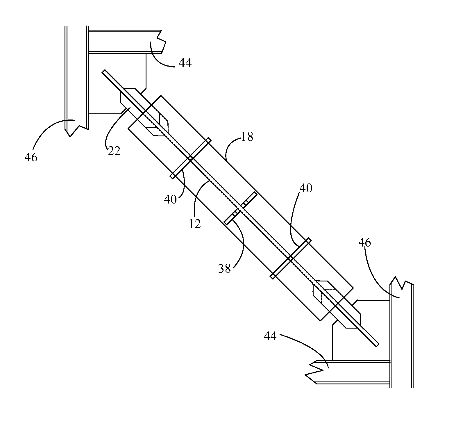
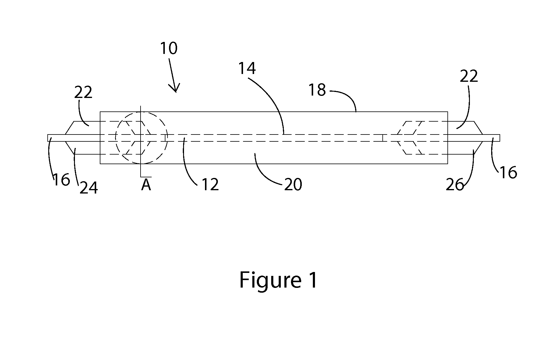
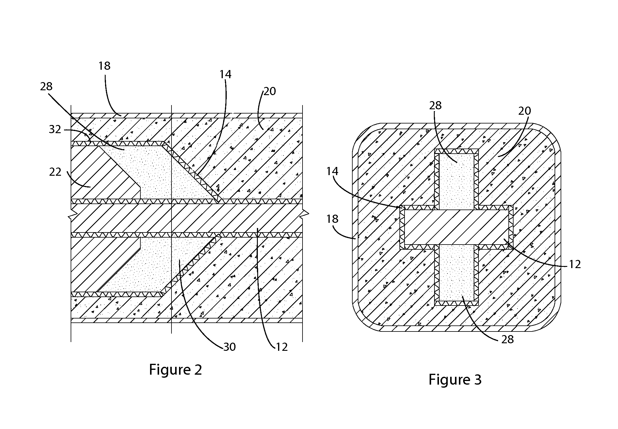
[0049]Shown in FIGS. 1 through 19 are several preferred embodiments of the Buckling restrained Brace of the disclosed technology. FIG. 1 shows the BRB 10 of the disclosed technology, including the core plate 12, a discrete spring layer 14, attachment means 16 on the ends of the core plate 12, the casing tube 18 and the grout matrix 20. Shown in FIG. 1 are stiffeners 22 which are attache...


PUM

PropertyMeasurementUnit
lengthaaaaaaaaaa
lengthaaaaaaaaaa
thicknessaaaaaaaaaa

Abstract

Disclosed is a buckling restrained brace which is a core plate inside a tube, with the plate prevented from buckling by being surrounded by the tube. The core plate is provided with a layer of discrete springs adjacent the core plate, with the interior of the tube otherwise filled with cement. The layer of discrete springs may be cardboard of other material. The layer of discrete springs defines a space between the core plate and the concrete, to allow for expansion of the core plate under compression from the ends.

Description

FIELD OF THE INVENTION[0001]This application is a continuation application of application Ser. No. 13 / 329,996 filed on Dec. 19, 2011, the disclosure of which is incorporated herein by reference.[0002]The disclosed technology is a brace for use in construction of structures, and more particularly a brace for use in absorbing impact, explosive or seismic forces and making a building or structure more resistant to these forces.BACKGROUND OF THE INVENTION[0003]A buckling restrained brace (BRB) is typically used in buildings or other structures to brace them from earthquake or other lateral forces. They are placed diagonally in buildings and are seen as sloping diagonal members running from floor to floor, sometimes visible in the building windows. A BRB is a structural brace meant to resist compression, and designed to not buckle. All other braces will buckle, similarly to a drinking straw, if you push axially on the ends of it. A BRB separates the buckling behavior from the load carryi...

Claims


Application Information

Patent Timeline
Patent Type & Authority Applications(United States)
IPC IPC(8): E04H9/02
CPCE04H9/02Y10T29/49623E04H9/028E04H9/021E04H9/0215E04H9/0237
Inventor HINCHMAN, ANDREW
Owner SEISMIC BRACING CO LLC
Why Eureka
Try Eureka