Interlocking laminated support mat

a technology of support mats and interlocking strips, which is applied in the direction of girders, single unit pavings, and ways, can solve the problems of difficult repair, flat tires of equipment, and difficulty in accessing with vehicles and equipment, and achieve the effect of facilitating the insertion of the load transfer tab

Inactive Publication Date: 2007-03-15
QUALITY MAT
View PDF40 Cites 44 Cited by
  • Summary
  • Abstract
  • Description
  • Claims
  • Application Information

AI Technical Summary

Benefits of technology

[0027] The load transfer slot of the mat unit may be wider that the load transfer tab to facilitate insertion of the load transfer tab into a load transfer slot of an adjacent mat unit. The number and configuration of the load transfer structures may be varie

Problems solved by technology

These conditions often make it difficult to access with vehicles and equipment necessary for the exploration and drilling operations.
The nails however can lead to flat tires of equipment, which are often difficult to have repaired due to the remote location of the site.
These systems thus require large amounts of time and manual labor to install and remove.
Additionally, individual boards are often damaged during removal such that they are unsuitable for reuse.
The wood panels are typically untreated with preservative chemicals because of environmental concerns.
Because the timber used to form the panel 10 is expensive, the panel 10 is very costly.
Further, the roadway formed by the panels 10 is very costly because tens of thousands of the panels 10 may be needed for a single construction project.
The use of multiple layer mats has been able to decrease the amount of labor and have been a benefit to the exploration and drilling for oil and gas, but some difficulties do exist in the construction of temporary roads and flooring.
The use of nails to fasten the mat layers together may lead to flat tires on equipment used in these remote areas.
This can be a difficult and frustrating problem because of the remote locations may make it difficult to have the tires repaired.
The weight of each individual multiple layer mat can also present a number of difficulties.
Additionally, the addition of a layer increases the overall size of the mat.
Increases in weight and size may increase both the transportation and the installation costs.
As the road is built, the distance between the storage location and the end of the road increases causing the equipment to travel farther between trips.
Thus, larger mats requ

Method used


Image

  • Interlocking laminated support mat
  • Interlocking laminated support mat
  • Interlocking laminated support mat

Examples


Embodiment Construction

[0038] Illustrative embodiments of the invention are described below as they might be employed in a laminated support mat. In the interest of clarity, not all features of an actual implementation are described in this specification. It will of course be appreciated that in the development of any such actual embodiment, numerous implementation-specific decisions must be made to achieve the developers' specific goals, such as compliance with system-related and business-related constraints, which will vary from one implementation to another. Moreover, it will be appreciated that such a development effort might be complex and time-consuming, but would nevertheless be a routine undertaking for those of ordinary skill in the art having the benefit of this disclosure.

[0039] Further aspects and advantages of the various embodiments of the invention will become apparent from consideration of the following description and drawings.

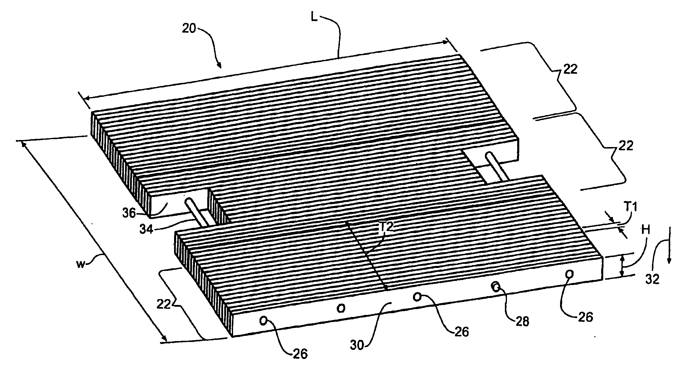
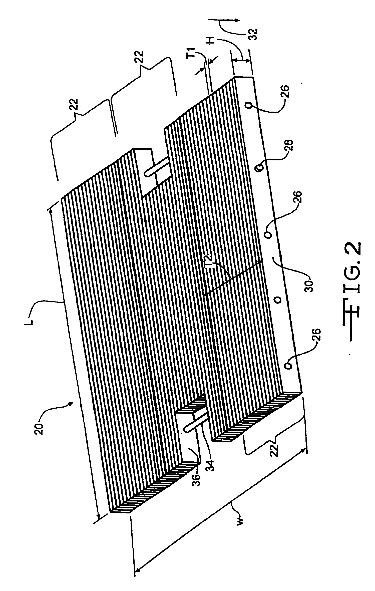
[0040] As shown in FIG. 2, a laminated support mat, indicate...


PUM

PropertyMeasurementUnit
Timeaaaaaaaaaa
Lengthaaaaaaaaaa

Abstract

A laminated one-ply support mat comprised of a plurality of individual wood hat includes means for transferring load and interlocking with an adjacent one-ply The laminated one-ply support mat may be suitable for the construction of ads, flooring, or platforms to support heavy equipment. The laminated one-ply ay include a non-laminated member fastened to each side to prevent damage to the laminated support mat. The laminated one-ply support may be comprised of a individual wood laminations fastened together by a plurality of nuts and bolts support mat to be disassembled and repair in the field.

Description

CROSS-REFERENCE TO RELATED APPLICATIONS [0001] This application is a continuation-in-part of co-pending U.S. patent application Ser. No. 11 / 011,724, filed Dec. 14, 2004, entitled “Laminated Support Mat,” which is a continuation-in-part application of U.S. patent application Ser. No. 10 / 377,099, filed Feb. 28, 2003, entitled “Method of Making Laminated Wood Beams With Varying Lamination Thickness Throughout the Thickness of the Beam,” which claims priority to U.S. provisional application Ser. No. 60 / 394,814, filed Jul. 10, 2002, each of which is incorporated herein in its entirety by reference.BACKGROUND OF THE INVENTION [0002] 1. Field of the Invention [0003] The present invention relates generally to an improved laminated one-ply support mat that may interlock with adjacent one-ply support mats to form a temporary road, platform, or flooring. The improved laminated one-ply support mat may be used as a support surface or pathway for heavy equipment to access remote areas to conduct ...

Claims


Application Information

Patent Timeline
IPC IPC(8): E04F15/00
CPCE01C5/14E01C9/086E04C3/14E04F2201/095E04F15/04E04F15/048E04C3/18
Inventor PENLAND, JOE E. SR.FUITAK, JON C.MCDOUGALL, SHANE M.PUTNAM, ALBERT P. III
Owner QUALITY MAT
Why Eureka
Try Eureka