Oil pan for engine

a technology for oil pans and engines, applied in the direction of machines/engines, liquid/fluent solid measurements, instruments, etc., can solve the problem of affecting the detection accuracy of changes that are detrimental to the effect of chang

Inactive Publication Date: 2007-03-15
HONDA MOTOR CO LTD
View PDF5 Cites 9 Cited by
  • Summary
  • Abstract
  • Description
  • Claims
  • Application Information

AI Technical Summary

Benefits of technology

[0008] The present invention has been achieved in view of the above-mentioned circumstances and has an aspect to prevent engine oil from entering an air hole of the oil sensor, thereby preventing the engine oil from detrimentally affecting the detection accuracy.
[0010] With the first feature, the air hole in the sensing section of the oil sensor is covered with the shield member. Therefore, the shield member prevents any splashed engine oil in the oil pan from entering the sensing section through the air hole, thereby enhancing the detection accuracy of the oil sensor.
[0012] With the second feature, the oil sensor is covered with the baffle plate and the air hole in the sensing section of the oil sensor is covered with the shield member extending downward from the lower surface of the baffle plate. Thus, any overheated or excited engine oil in the oil pan is suppressed by the baffle plate to prevent the oil from splashing, and any splashed engine oil is prevented from entering the sensing section through the air hole, thereby enhancing the detection accuracy of the oil sensor. Moreover, since the shield member is supported on the baffle plate, an additional component or member dedicated to support the shield member is not required.
[0014] With the third feature, the shield member has a tubular portion surrounding the sensing section of the oil sensor. Therefore, any splashed oil originating from the periphery of the oil sensor is reliably shielded by the shield member, thereby preventing the splashed oil from entering the air hole.
[0016] With the fourth feature, the clearance for venting air is formed between the baffle plate and the tubular portion of the shield member for covering the air hole in the sensing section. Therefore, even if the lower end of the tubular portion is submerged in the engine oil and the tubular portion is sealed, the clearance prevents the internal pressure of the tubular portion from changing, thereby securing the detection accuracy of the oil sensor.
[0018] With the fifth feature, the shield member is arranged to shield the oil sensor from a balancer device provided in the oil pan. Therefore, the shield member reliably blocks any splashed oil generated by operating the balancer device, thereby preventing the splashed oil from entering the air hole.

Problems solved by technology

Therefore, if the engine oil in the oil pan rampages and generates a splash, wherein the splashed oil enters the sensing section through the air hole, the level of engine oil in the sensing section changes, leading to a possibility that such a change detrimentally affects the detection accuracy.

Method used


Image

  • Oil pan for engine
  • Oil pan for engine
  • Oil pan for engine

Examples


Embodiment Construction

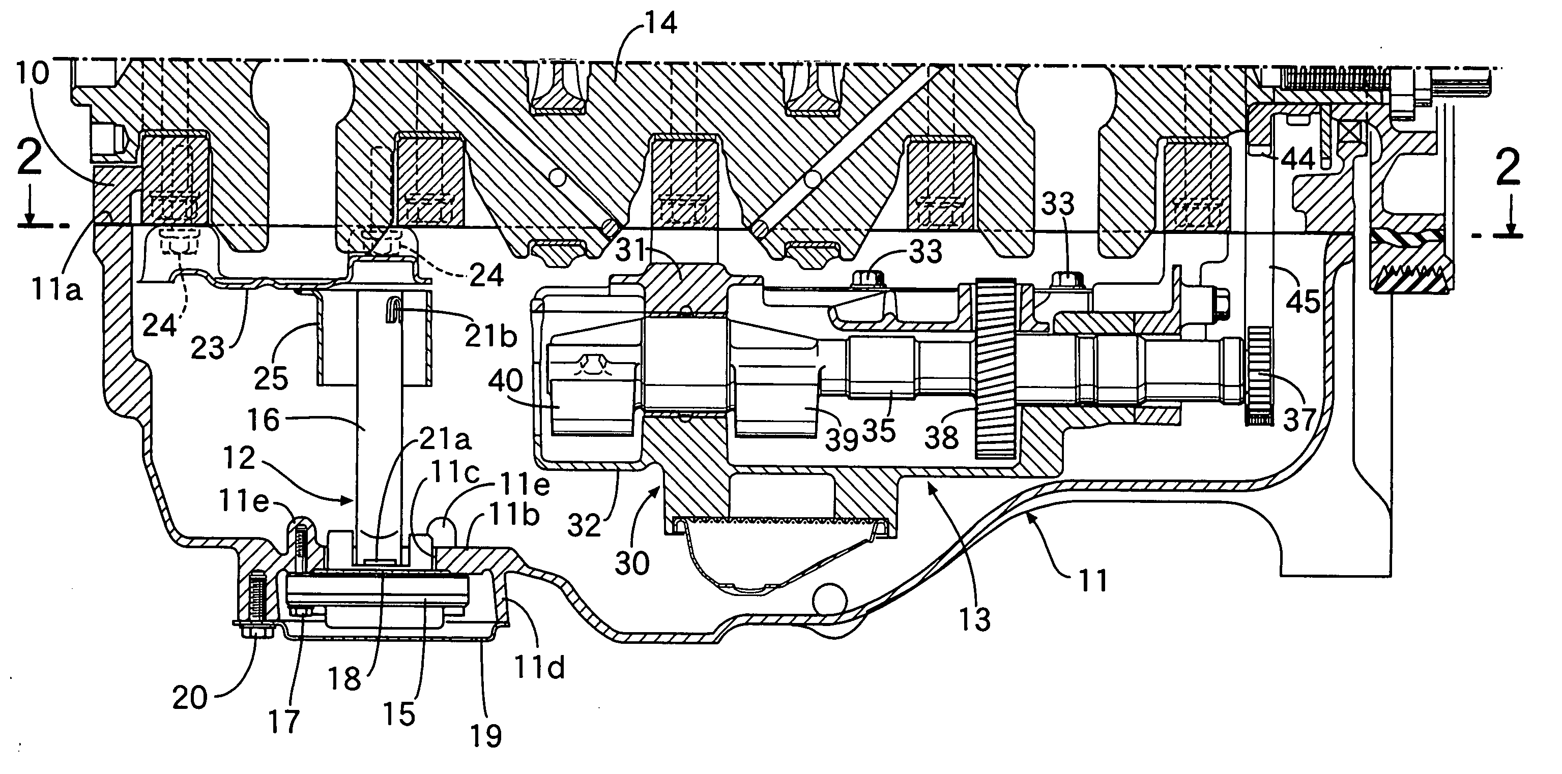
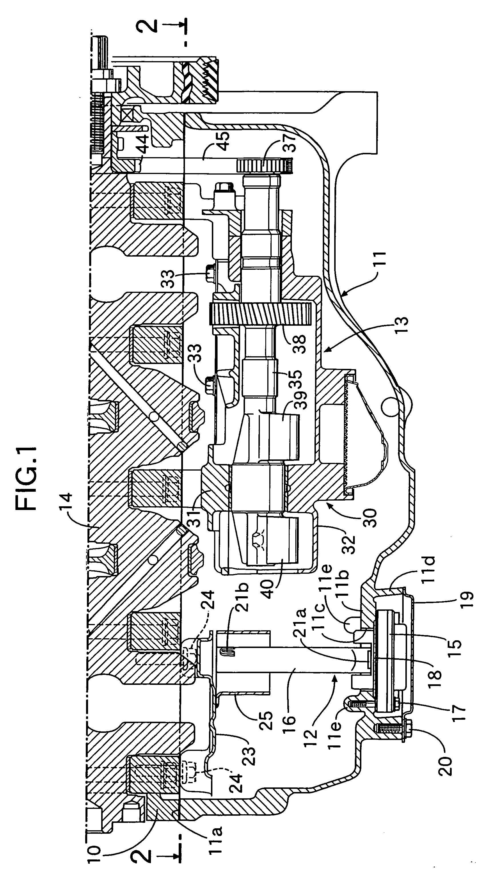
[0024] As is apparent from FIG. 1, an oil pan 11 is attached to a lower surface of a cylinder block 10 of an automobile diesel engine. The oil pan 11 is a vessel-shaped member having, along a peripheral edge of an upper surface opening, a mounting surface 11a for mounting the oil pan 11 to the cylinder block 10. An oil level sensor 12, which detects the oil level in the oil pan 11, is provided on one end side of the oil pan 11 in the longitudinal direction. A balancer device 13 is provided on the other end side of the oil pan 11 in the longitudinal direction. A crankshaft 14 is rotatably supported on the cylinder block 10.

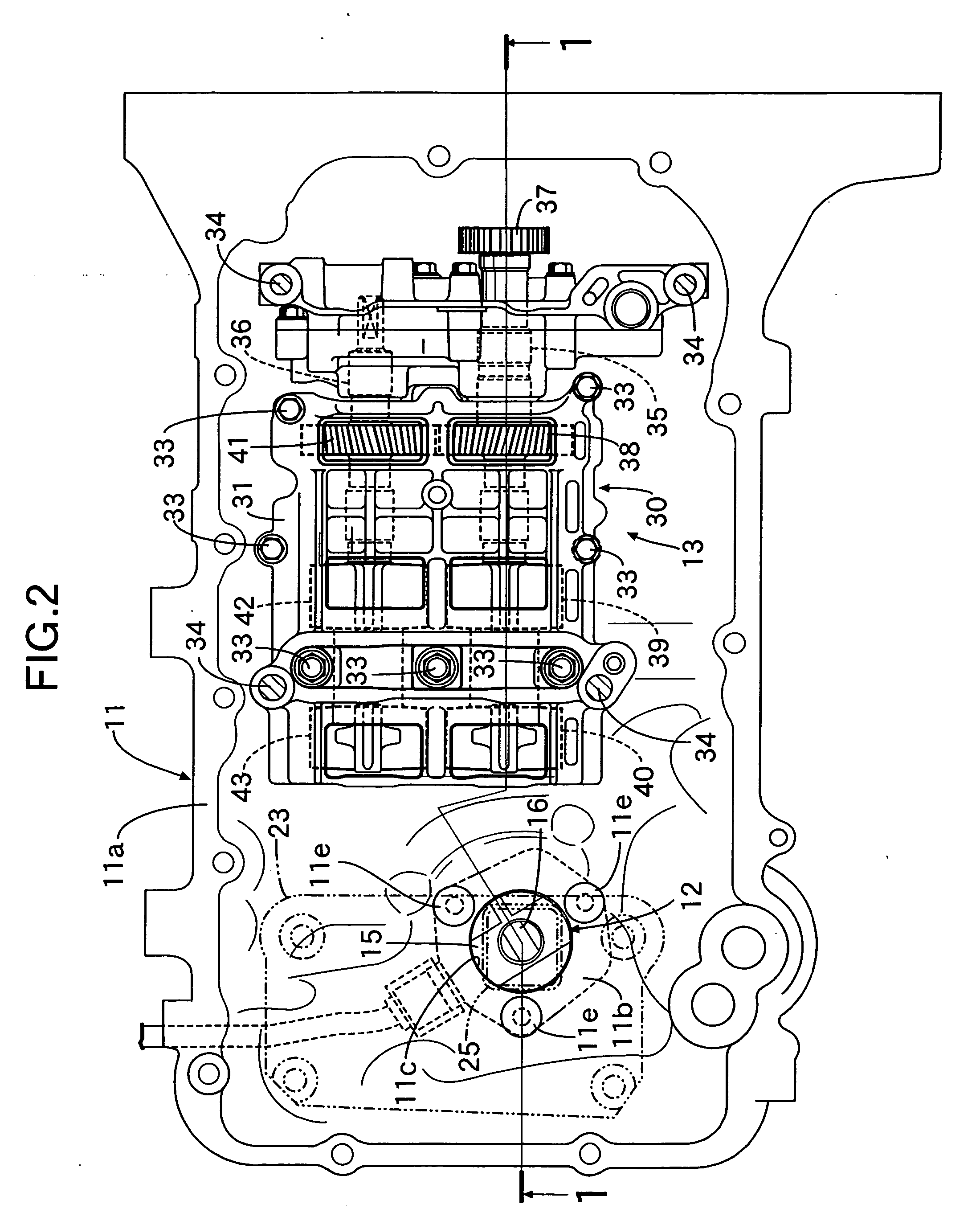
[0025] As is apparent from FIGS. 1 to 3, a circular sensor mounting opening 11c is formed in a center of a sensor mounting portion 11b of the oil pan 11. An annular rib 11d is projectingly provided on the lower surface of the oil pan 11 and surrounds the sensor mounting opening 11c. The oil level sensor 12 has a mounting section 15 shaped like a hexagonal box when...


PUM

PropertyMeasurementUnit
temperatureaaaaaaaaaa
heataaaaaaaaaa

Abstract

An oil level sensor for detecting an oil level is arranged in an engine oil pan. The oil level sensor includes a mounting section and a sensing section. An air hole is formed at an upper end of a cover member of the sensing section. The air hole is surrounded by a tubular portion of a shield member attached to a baffle plate of the oil pan. Therefore, any splashed engine oil in the oil pan is restricted from entering the cover member of the sensing section through the air hole. Also, a clearance (α) for venting air is formed between the tubular portion and the baffle plate.

Description

RELATED APPLICATION DATA [0001] The present invention is based upon Japanese priority application No. 2005-261587, which is hereby incorporated in its entirety herein by reference. BACKGROUND OF THE INVENTION [0002] 1. Field of the Invention [0003] The present invention relates to an oil pan for an engine located below a cylinder block of the engine to store engine oil and in which an oil sensor for detecting a parameter of the engine oil is disposed. [0004] 2. Description of the Related Art [0005] Japanese Patent Application Laid-open No. 2003-83935 (JP '935) discloses an oil pan having an oil deterioration sensor in a bottom portion thereof for determining a time to change the engine oil for an automobile engine. The oil deterioration sensor detects the degree of deterioration of the engine oil based on a pH value. The oil deterioration sensor includes a sensing section for housing therein a sensing element, and a mounting section for supporting the sensing section. The sensing se...

Claims


Application Information

Patent Timeline
Patent Type & Authority Applications(United States)
IPC IPC(8): G01N33/26F02B77/00
CPCF01M11/10G01F23/246G01F23/22
Inventor FUJIKI, KENJIMURAKAMI, OSAMUUENO, MASAYUKIKANEHIRO, MASAKIKOSAKA, SEIJI
Owner HONDA MOTOR CO LTD
Why Eureka
Try Eureka