Photovoltaic module

a photovoltaic module and photovoltaic technology, applied in the direction of heat collector mounting/support, light radiation electric generator, lighting and heating apparatus, etc., can solve the problems of increasing the manufacturing cost of the connection, the terminal box disposed on the expanded part of the glass cannot be adapted to a type of photovoltaic module, and the failure of the insulation, etc., to achieve favorable appearance of the photovoltaic modul

Active Publication Date: 2007-03-15
PANASONIC INTELLECTUAL PROPERTY MANAGEMENT CO LTD
View PDF8 Cites 43 Cited by
  • Summary
  • Abstract
  • Description
  • Claims
  • Application Information

AI Technical Summary

Benefits of technology

[0022] According to the above structure, the printed area can keep the adhesive used for attaching the terminal box to the rear surface member out of view from the side of the light-rec

Problems solved by technology

Usually, the terminal box is attached in the final process because the terminal box is obstructive during the production process of the module.
However, damage to the insulating coating of the connection leads 55 could cause an insulation failure.
Thus, the conventional insulating coating needs to be thick enough to prevent the insulation failure caused by the

Method used


Image

  • Photovoltaic module
  • Photovoltaic module
  • Photovoltaic module

Examples


first embodiment

[0039]FIG. 4 is a schematic cross-sectional view illustrating a solar cell used in the present invention. FIG. 5 is a schematic structural diagram of manufacturing equipment for manufacturing photovoltaic submodules used in the present invention. FIG. 6 is a cross-sectional view of a photovoltaic submodule used in the photovoltaic module according to the present invention.

[0040]FIG. 7 is a plan view illustrating a part of the connection leads of the photovoltaic submodule used in the present invention. FIG. 8 is an exploded perspective view of a terminal box used in the first embodiment of the present invention. FIG. 9 is a perspective view illustrating the terminal box used in the first embodiment of the present invention. FIG. 10 is a plan view illustrating the terminal box attached to the photovoltaic submodule.

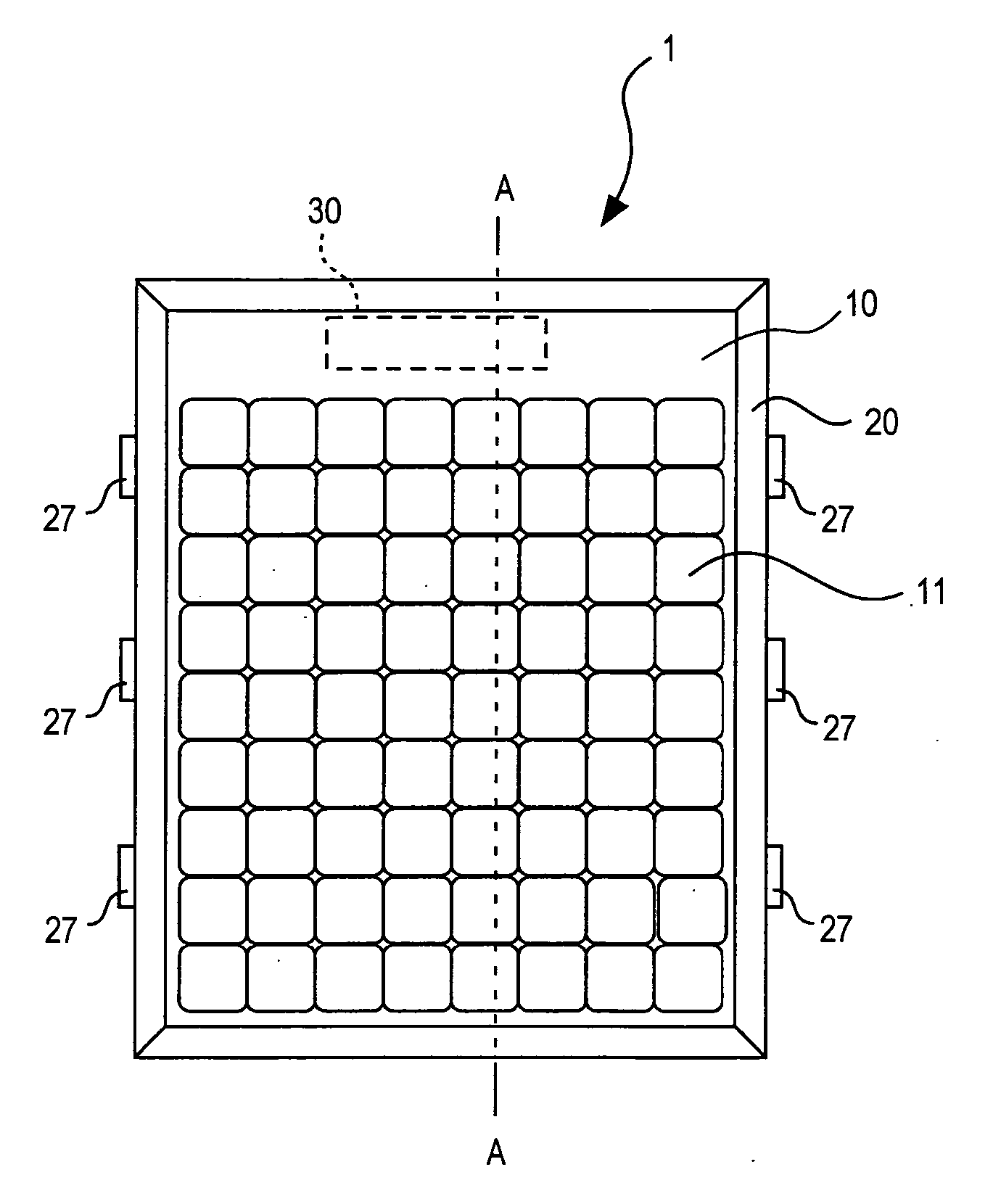
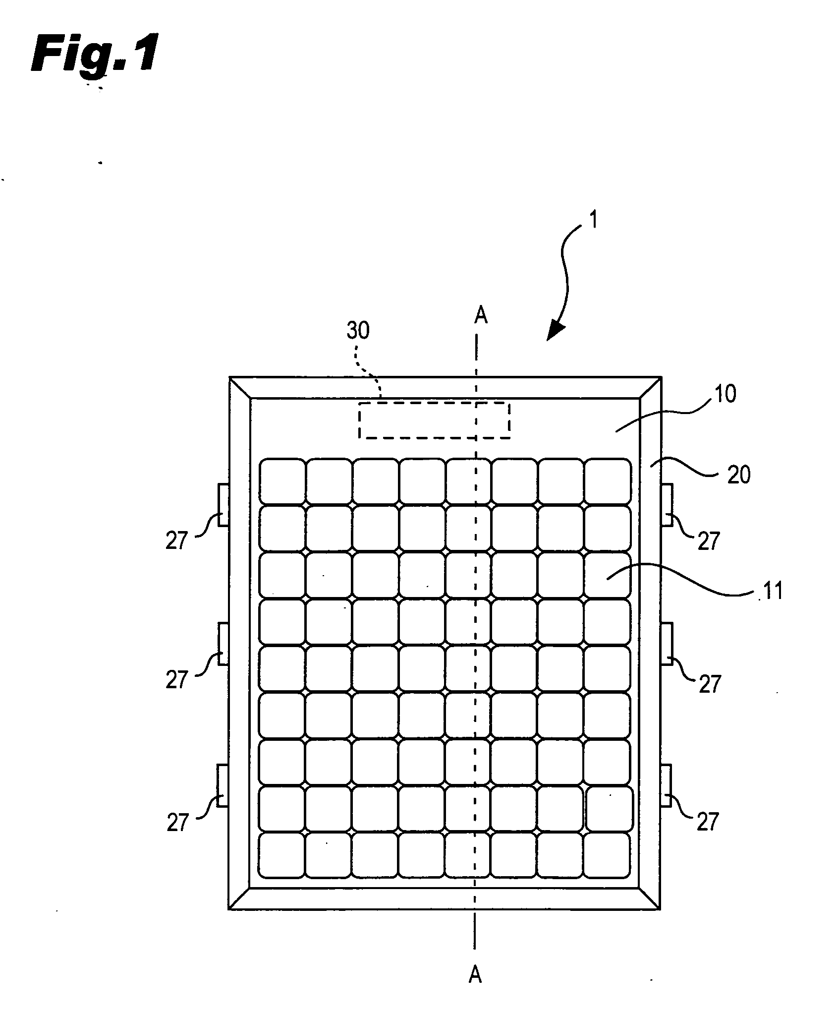
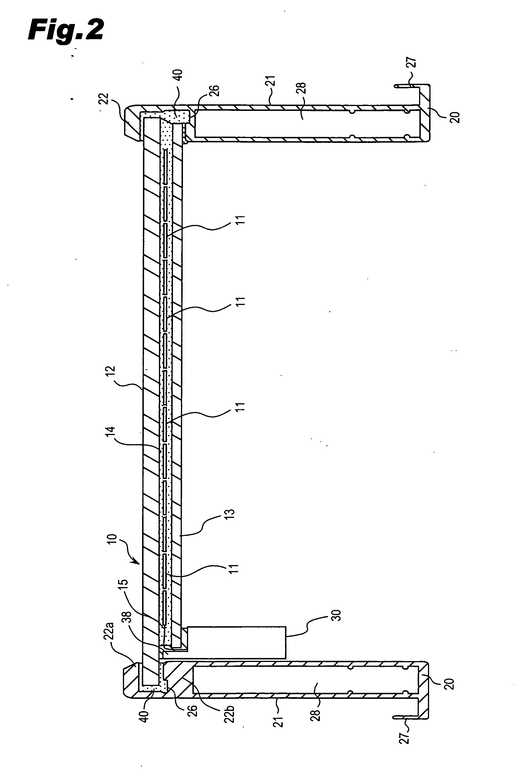
[0041] As shown in FIGS. 1-3, the photovoltaic module 1 of the present invention comprises a rectangular double-sided light receiving type photovoltaic submodule 10 inclu...

second embodiment

[0078] As shown in FIG. 11, in the photovoltaic module 1a of the second embodiment, dummy cells 11a are placed, as if the solar cells 11 are arranged orderly, in the region on the light-transmitting substrate 12 and above the terminal box 30, in which the solar cells are not provided. This arrangement of the dummy cells 11a enhances the design of the photovoltaic module 1. The dummy cells 11a can be stuck or printed at predetermined positions on the light-transmitting substrate 12.

[0079] If the dummy cells 11a are subjected to a treatment so as to irregularly reflect light, which would have passed through the photovoltaic submodule 10 without the dummy cells 11a, into the solar cells 11, the photovoltaic module 1 can improve the utilization efficiency of light.

third embodiment

[0080]FIG. 12 is a cross-sectional view of a relevant part of a photovoltaic module according to the present invention.

[0081] As illustrated in FIG. 12, the terminal box 30 is attached near the outmost edge of the rear surface side light-transmitting substrate 13 of the photovoltaic submodule 10. A printed area (a colored area) 19 is provided on the light-receiving side light-transmitting substrate 12 and above the terminal box 30. As illustrated in FIG. 12, the printed area 19 can hide the adhesive used for attaching the terminal box 30 to the rear surface side light-transmitting substrate 13 when viewed from the light-receiving side. The terminal box 30 can be made invisible too from the light-receiving side, which makes it more aesthetically pleasing of the photovoltaic module.

[0082] The printed area 19 does not need to be shaped like the dummy cell but can have any shape as long as the printed area can serve as a masking part for hiding the terminal box 30 and other parts. The ...


PUM

PropertyMeasurementUnit
Coloraaaaaaaaaa
Currentaaaaaaaaaa
Lightaaaaaaaaaa

Abstract

This invention provides a photovoltaic module for preventing insulation failure between an outer frame and connection leads. The photovoltaic module comprises: a photovoltaic submodule including a plurality of solar cells interposed between two light-transmitting substrates through the intermediary of an encapsulant and the connection leads extending from an edge between light-transmitting substrates and outputting generated electric currents; a terminal box attached near an edge of the photovoltaic submodule and housing connected parts between the connection leads and cables for outputting the electric currents to the outside; and an outer frame fitting over peripheral edges of the photovoltaic submodule. A side, of the light-receiving side light-transmitting substrate, from which the connection leads are pulled out, is made large so as to extend outward further than the other light-transmitting substrate. The connection leads are led out from the edge between the two light-transmitting substrates to be guided into the terminal box.

Description

[0001] The priority application Number JP2005-265428 upon which this patent application is based is hereby incorporated by reference. BACKGROUND OF THE INVENTION [0002] 1. Field of the Invention [0003] The present invention relates to a photovoltaic module, and is particularly suitable for a double-sided light receiving type photovoltaic module which receives light on both sides. [0004] 2. Description of the Prior Art [0005] Photovoltaic power generation which converts light energy into electric energy by utilizing the photoelectric conversion effect is widely used as a means to obtain clean energy, which contributes to the preservation of the global environment. With the improvement in solar cells' photoelectric conversion efficiency, many photovoltaic power generation systems with photovoltaic modules have come to be installed even for residential use. [0006] In order for a photovoltaic module provided with solar cells generating electric power from sunlight to output the generate...

Claims


Application Information

Patent Timeline
IPC IPC(8): H02N6/00
CPCF24J2/5211H01L31/02008H01L31/042H01L31/048Y02E10/47H02S40/34B32B17/10036B32B17/10091B32B17/10788B32B17/10871Y02E10/50H01L31/02013H02S30/10F24S25/20H01L31/00
Inventor HIGUCHI, MINORUHIKOSAKA, MASARUNAKAUCHI, ATSUSHIODA, HIROYUKIOKAMOTO, SHINGO
Owner PANASONIC INTELLECTUAL PROPERTY MANAGEMENT CO LTD
Why Eureka
Try Eureka