Eureka AIR delivers breakthrough ideas for toughest innovation challenges, trusted by R&D personnel around the world.

Image forming apparatus

Active Publication Date: 2007-03-15
CANON KK
View PDF14 Cites 14 Cited by
  • Summary
  • Abstract
  • Description
  • Claims
  • Application Information

AI Technical Summary

Benefits of technology

[0012] Thus, according to the present invention, timing information is transferred from the image forming apparatus to the sheet processing apparatus. The timing information is edited successively by taking into consideration the preparation time and the like on each sheet processing apparatus. That is, by considering the sheet processing apparatus up to the one which actually processes the sheet instead of considering all the sheet processing apparatus connected to the image forming apparatus, it is possible to achieve a higher processing efficiency than the former case.

Problems solved by technology

For example, if the image forming apparatus or an upstream sheet processing apparatus discharges a sheet to a sheet processing apparatus connected downstream even though the downstream sheet processing apparatus is not ready, troubles such as paper jam will occur.
However, this method can delay the timing of discharge and slow down the printing process if the last sheet processing apparatus is not in use.
This results in low processing efficiency.

Method used


Image

  • Image forming apparatus
  • Image forming apparatus
  • Image forming apparatus

Examples


example

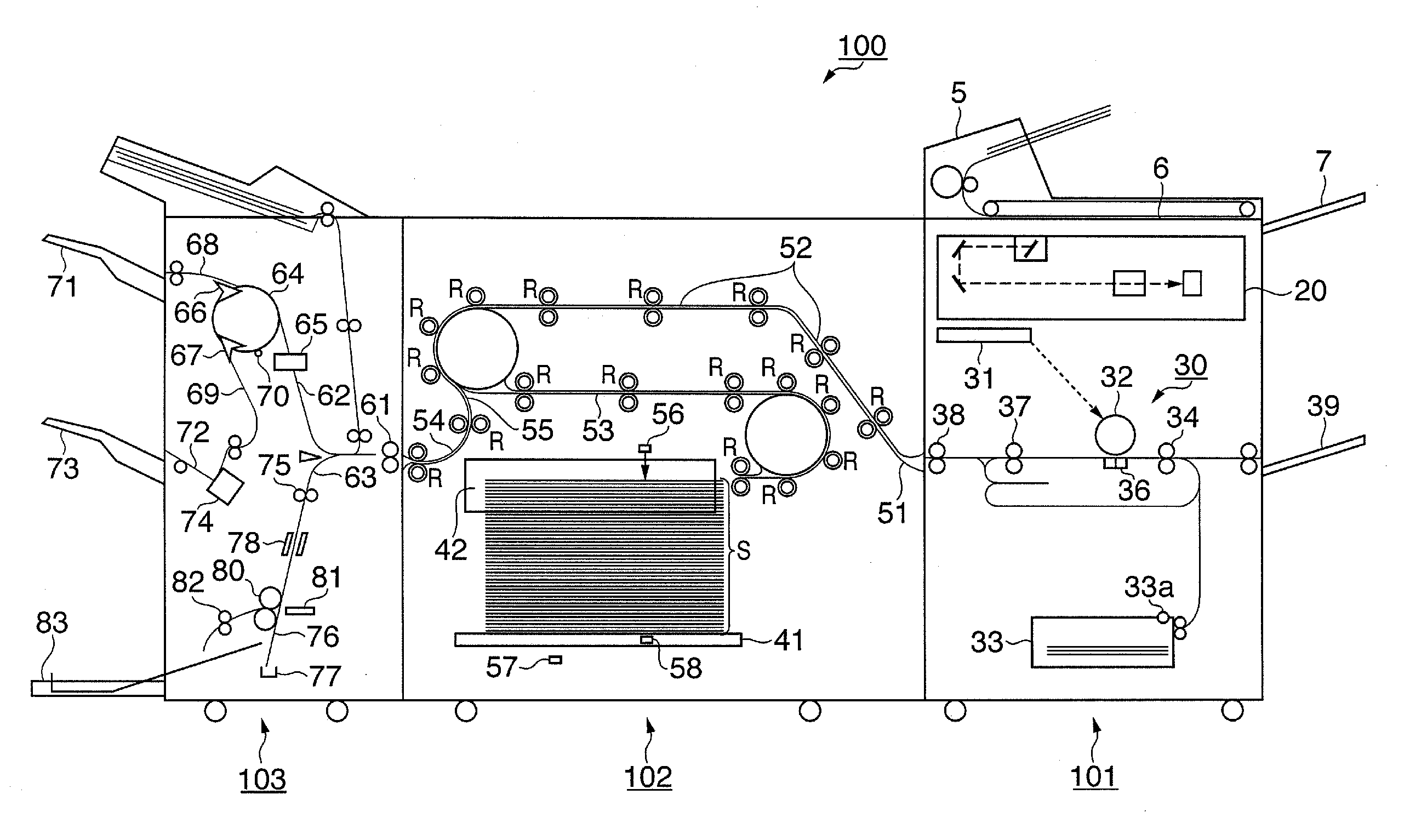
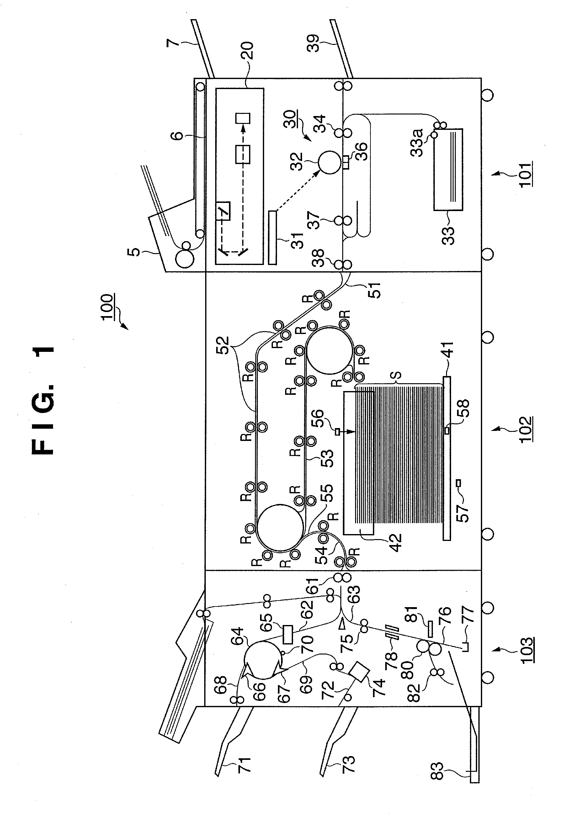
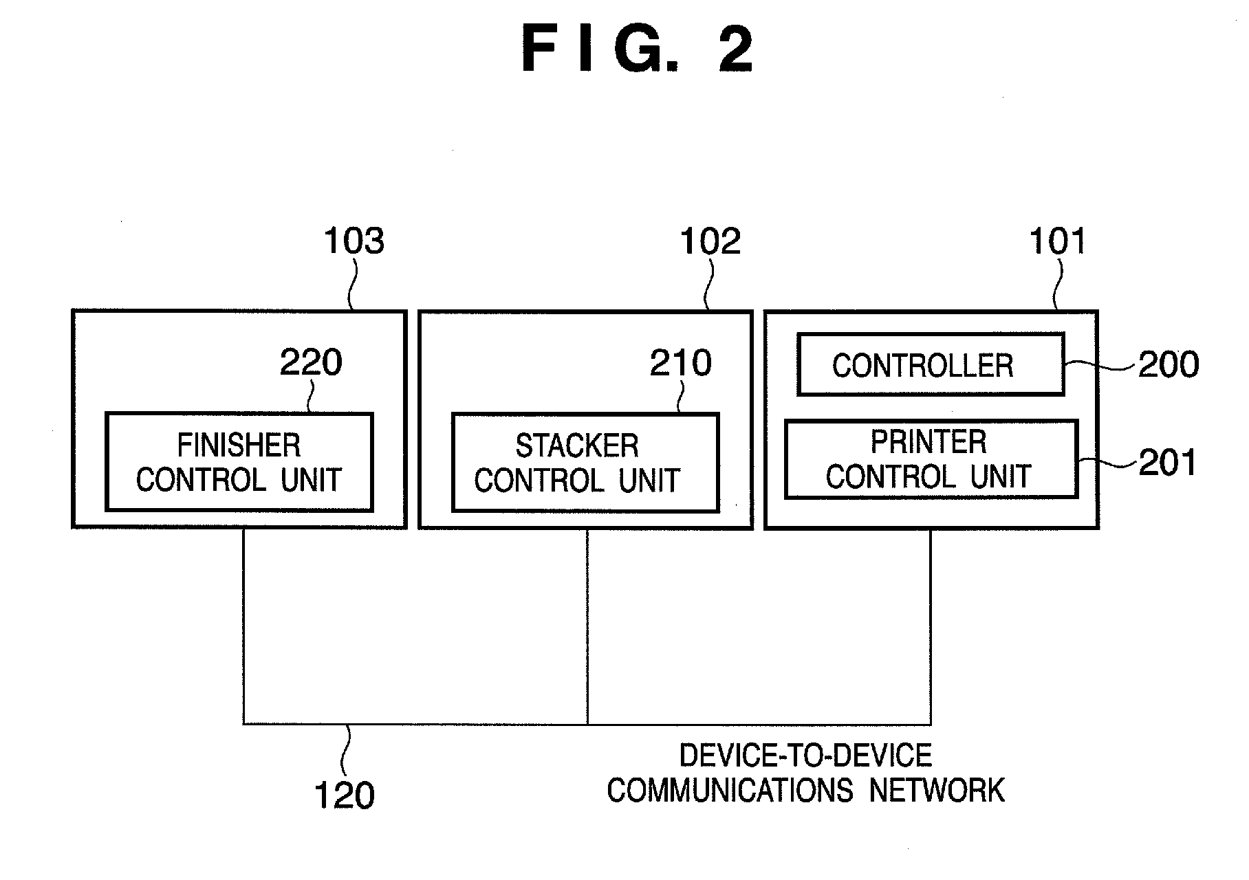
[0113] The control method of the sheet discharge timing described so far will be described citing concrete figures. Description will be given here of an example in which three sheets (SID=1, 2, 3) are stacked on different sheet processing apparatus. It is assumed here that the first sheet (SID=1) is stacked on the finisher 103, that the second sheet (SID=2) is stacked on the stacker 102, and that the third sheet (SID=3) is stacked on the finisher 103.

[0114]FIG. 10 is a diagram showing an example of timing information about the first sheet. FIG. 11 is a diagram showing an example of timing information about the second sheet. FIG. 12 is a diagram showing an example of timing information about the third sheet.

[0115] It is assumed that the time [T pas,s] required to transit through the stacker 102 is 800 ms, that the time [T prp,s] required for preparation of the stacker 102 is 300 ms, and that the time [T prc,s] required for processing on the stacker 102 is 300 ms. Also, it is assume...


PUM


Abstract

Timing information for use to determine the timing to discharge a sheet from an image forming apparatus is transmitted. The timing information is relayed, by being edited repeatedly, from a first sheet processing apparatus connected directly with the image forming apparatus to a second sheet processing apparatus which actually processes the sheet. The timing information is edited on each sheet processing apparatus by considering, for example, transit time of the sheet, processing time of the sheet, preparation time for the sheet to get ready to be processed, and the like. The second sheet processing apparatus transmits the timing information to the image forming apparatus. The image forming apparatus determines the discharge timing of the sheet based on the received timing information and discharges the sheet with the determined discharge timing.

Description

[0001] This application claims the benefit of Japanese Patent Application Nos. 2005-264432, filed Sep. 12, 2005, and 2006-220644, filed Aug. 11, 2006, which are hereby incorporated by reference herein in their entirety.BACKGROUND OF THE INVENTION [0002] 1. Field of the Invention [0003] The present invention relates to an image forming apparatus which uses a plurality of sheet processing apparatuses equipped with sheet processing functions and arranged and connected serially. [0004] 2. Description of the Related Art [0005] Conventionally, an image forming apparatus connected with sheet processing apparatuses such as a finisher and sorter (sometimes called post-processing units) have been used for personal purposes and business purposes. Today, however, along with improvements in the image quality and increase in the speed of image forming apparatus, they are coming into use in the print industry as well. [0006] In the print industry, various types of sheet processing (post-processing...

Claims


Application Information

Patent Timeline
IPC IPC(8): B65H7/02
CPCB65H43/00B65H2511/414B65H2513/50B65H2513/51G03G15/6529G03G2215/00599G03G2215/00603B65H2220/01B65H2220/03G03G15/00
Inventor NISHIMURA, SHUNSUKEYAMAUCHI, MANABUWATANABE, NAOTOFUJII, TAKAYUKISATO, MITSUHIKOSUNADA, HIDENORISASAKI, ICHIRONISHIKATA, AKINOBU
Owner CANON KK
Why Eureka
Eureka Blog
Learn More