
Onsite steel rail laser processing vehicle

Active Publication Date: 2015-01-22
WUHAN HIVALUE INTELASER LTD
View PDF15 Cites 10 Cited by
  • Summary
  • Abstract
  • Description
  • Claims
  • Application Information

AI Technical Summary

Benefits of technology

The present invention provides an on-line laser processing vehicle for rail that can precisely control running speed and distance of the vehicle during processing, thus achieving accurate processing along a rail route. This improves wear resistance of the rail and meets requirements of high-speed and heavy haul trains for wear resistance. The vehicle has a dual driving system and switching mechanism that allows for precise control of the moving speed and distance of the vehicle during laser processing. The chassis of the vehicle can be a chassis of a railway flat-deck car, a railway passenger car, or a convertible road-railway vehicle, and a climbing-rail system can be added for improved flexibility. The movement actuator can be a conventional numerical controlled machine tool or a multi-axis industrial robot, and a photoelectric displacement sensor can be used to ensure accuracy of the processing trajectory. The vehicle has three types of laser processing heads: a mechanical laser processing head, a multiple-light-outlet-type laser processing head, and a galvanometer-type laser processing head, providing different processing efficiency requirements.

Problems solved by technology

Along with increase of train speed, traffic volume and axle loading, the rate of wear-out failure for a rail increases dramatically due to a dual effect of impact and wear caused by wheels.
The conventional method can only be accomplished in workshops; however, besides the laser surface strengthening method can facilitate fixed-point processing in workshops, the specific mobile equipment can be developed in order to take laser processing equipments into the railway field for on-line laser treating on rail.
Firstly, the device uses the high-power CO2 laser as a light source; the photoelectric conversion efficiency thereof is relatively low, while energy consumption thereof is high. The wavelength of the CO2 laser is 10.6 microns, therefrom the absorption of a metal substrate to that is quiet low, and the procedure is comparatively complicated because the laser processing cannot be carried out until light-absorbing coatings are sprayed thereon and dried. Since a light-guide system of the CO2 laser can only use a flying light path or a hard-light-path system for transmission, precision of the light-guide system may be inevitably affected by vibration generated by the laser maintenance vehicle during operation, and it is difficult to ensure long-term stability of laser processing.
Secondly, when the device carries out laser maintenance, the laser maintenance vehicle is stationary, and the maximum distance for a laser processing head moving along the rail is 1000 mm. The distance of a rail processed by the laser processing head at one time is limited by the length of the body of the laser maintenance vehicle due to the coming to a standstill of the laser maintenance vehicle, and thus making it inconvenient for long-distance repairing. Further, when the laser vehicle is to arrive to the next section of a rail to be repaired, since a movement distance of the traction-control vehicle cannot be accurate to centimeters, it is difficult for the traction-control vehicle to be precisely located.
Thirdly, compared with the concerned accurate trajectories required for laser processing, the overall accuracy of a railway line in a railway field is good, but an actual rail is a curve line erratically fluctuated along an overall route. A position of the laser processing head can not be adjusted in real time in the invention, thus it is difficult to ensure for the laser processing head to guarantee an accuracy of hardening a processing path.
Firstly, the small laser processing trolley and the power engineering vehicle are two separated parts, the maximum distance of an interconnected fiber or a cable is 100 meters, which increases complexity of the device used in railway field; compared with a complete set of integrated equipment system, its reliability thereof is relatively low.
Secondly, although the small laser processing trolley is small volume, light weight and good flexibility, manpower or a small forklift is required to install it on a track, and connection and device adjustment of the fiber or the cable system need to be conducted on the track, therefore, effective time and processing efficiency of laser strengthening-toughening treatment on railway track are affected.
Thirdly, the way of approaching the railway track by the power engineering vehicle of the on-line laser processing device is sometimes limited. In some special places (such as mountain railways), the power engineering vehicle cannot conveniently approach railway tracks, and wheel systems thereof cannot directly travel thereon, which result in limitation of the combined type small laser processing trolley and power engineering vehicle on line laser processing device in terms of application range and efficiency.

Method used


Image

  • Onsite steel rail laser processing vehicle
  • Onsite steel rail laser processing vehicle
  • Onsite steel rail laser processing vehicle

Examples


first embodiment

[0043]The first embodiment is an on-line laser processing vehicle for rail according to the present invention.

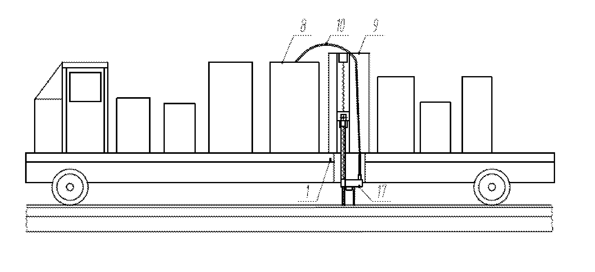
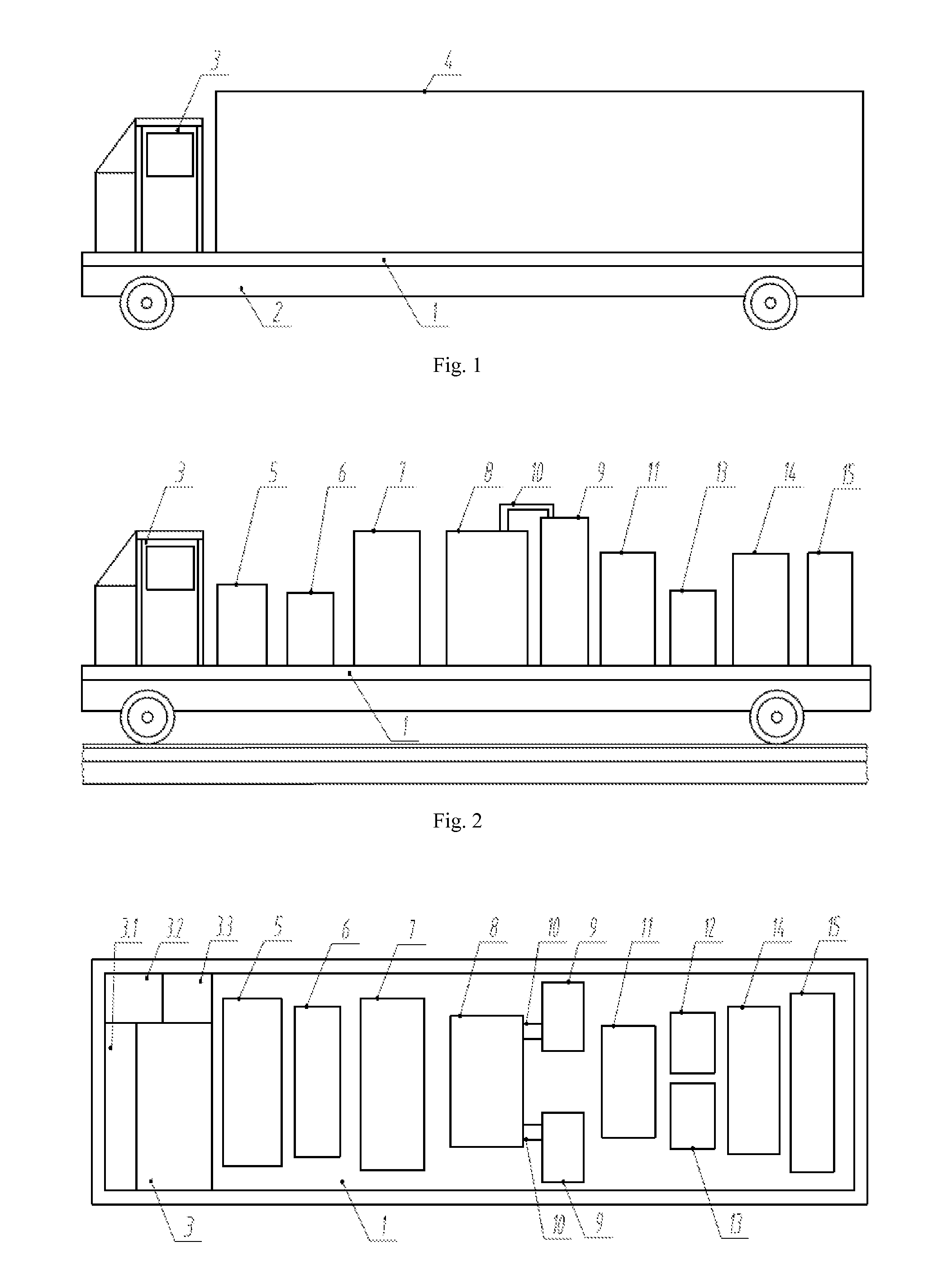
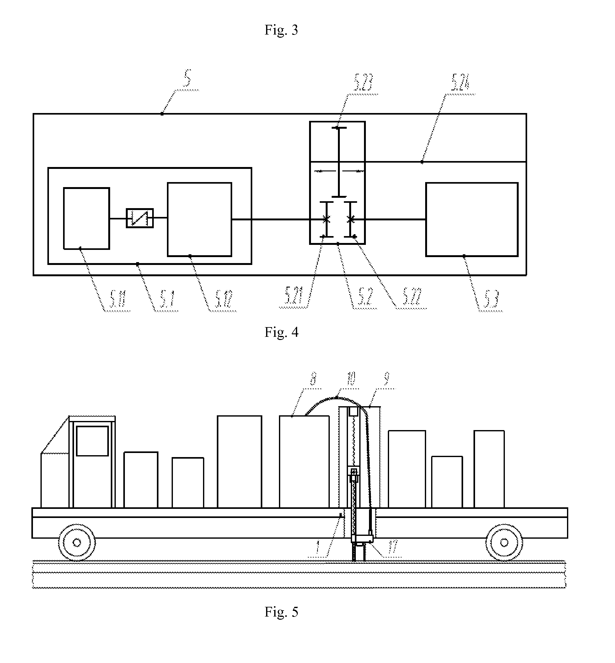
[0044]As shown in FIGS. 1 and 3, the laser processing vehicle comprises a vehicle body 1, a chassis 2, a steer-control chamber 3 disposed in front of the vehicle body 1, and a container 4 disposed at the rear of the vehicle body 1. The vehicle body 1 is disposed on the chassis 2, the chassis 2 is a chassis of a railway flat-deck car or a railway passenger car, and a transmission system for power transmission, a railway coupling-wheel system for running on the rail, and a turning and braking system are disposed at the bottom thereof. Besides a normal steering system, the steer-control chamber 3 comprises a console 3.1, a CCD monitoring system 3.2, and a drive-switching operating system 3.3. As shown in FIGS. 2 and 3, a dual driving and switching mechanism 5, a grinding and cleaning equipment 6, a chiller 7, a laser group 8, a movement actuator 9, a light-guide system 10, a po...

second embodiment

[0064]The second embodiment is a convertible road-railway laser processing vehicle according to the present invention.

[0065]As shown in FIG. 11, difference of the second embodiment from the first embodiment is the chassis of the used laser processing vehicle, the second embodiment uses a chassis of a respective-running-type convertible road-railway vehicle 20, so that the laser processing vehicle is capable of traveling on a railway or a road. As the chassis of the respective-running-type convertible road-railway vehicle 20 is used, the conventional operation driving system 5.3 of the dual driving and switching mechanism 5 is a driving system of a convertible road-railway vehicle; the steer-control chamber 3 is changed correspondingly: the conventional operation driving system therein is changed to a conventional operation driving system for the convertible road-railway vehicle; in addition, the console 3.1, the CCD monitoring system 3.2 and the drive-switching operating system 3.3 ...

third embodiment

[0067]The third embodiment is another form of the convertible road-railway laser processing vehicle according to the present invention.

[0068]As shown in FIG. 12, difference of the third embodiment from the second embodiment is that climbing-rail systems 16 and 16′ are added to the chassis of the respective-running-type convertible road-railway vehicle 20. Since the climbing-rail systems 16 and 16′ use hydraulic cylinders, a hydraulic system is disposed in the container 4, meanwhile, an operation platform operating to control the climbing-rail systems 16 and 16′ and the hydraulic system is disposed in the steer-control chamber 3. Other parts of the convertible road-railway laser processing vehicle are the same as those of the first embodiment.

[0069]As shown in FIG. 13a, the climbing-rail system 16 comprises four lifting devices and a transverse expanding device 16.5, the four lifting device are a first lifting device 16.1, a second lifting device 16.2, a third lifting device 16.3 and...


PUM


Abstract

The invention discloses an on-line laser processing vehicle for a rail, including a chassis, a vehicle body, a steer-control chamber and a container; the steer-control chamber includes a console, a CCD monitoring system and a drive-switching operating system; a dual driving system and switching mechanism, which with a process-operation driving system, a conventional operation driving system and a switching mechanism, is disposed in the container; the process-operation driving system operates to provide driving power for the laser processing vehicle during laser processing, and precisely controls moving speed and distance of the laser processing vehicle; the switching mechanism operates to implement switching between the conventional operation driving system and the process-operation driving system. The invention ensures accurate processing trajectories of the laser processing vehicle during laser processing; facilitates on-line laser processing of a variety of rails, such as the rails of main line, curved rails, guard rails, switch rails and so on, so that wear resistance of the processed rail is greatly improved, and meets requirements of high-speed and heavy haul trains for wear resistance of the rail.

Description

FIELD OF THE INVENTION[0001]The present invention relates to the technical field of surface strengthening and repairing for a rail, and more particularly to an on-line laser processing vehicle for a rail.BACKGROUND OF THE INVENTION[0002]Along with increase of train speed, traffic volume and axle loading, the rate of wear-out failure for a rail increases dramatically due to a dual effect of impact and wear caused by wheels. Conventional methods for improving life of rails throughout the world mainly focus on two aspects, namely heat treatment methods for rail and rail materials. With rapid development of laser technologies, methods of laser surface strengthening have been applied to rail for surface treating by domestic and foreign scholars, and good experimental results have been achieved.[0003]The conventional method can only be accomplished in workshops; however, besides the laser surface strengthening method can facilitate fixed-point processing in workshops, the specific mobile ...

Claims


Application Information

Patent Timeline
IPC IPC(8): E01B31/18B60F1/00B61D15/00
CPCE01B31/18B61D15/00B60F1/00B60F1/04B60F2301/02B60F2301/10B61K9/08
Inventor ZENG, XIAOYANHU, QIANWULI, CHONGYANGZHENG, YINLANDU, MIN
Owner WUHAN HIVALUE INTELASER LTD
Learn More