Eureka AIR delivers breakthrough ideas for toughest innovation challenges, trusted by R&D personnel around the world.

Sheet post-processing apparatus

a post-processing apparatus and sheet technology, applied in the field of sheet post-processing apparatus, can solve the problems of increased size and cost of the device, inefficient post-processing operation, complicated device configuration, etc., and achieve the effect of simplifying the feeding path

Inactive Publication Date: 2009-03-03
KYOCERA DOCUMENT SOLUTIONS INC
View PDF8 Cites 13 Cited by
  • Summary
  • Abstract
  • Description
  • Claims
  • Application Information

AI Technical Summary

Benefits of technology

[0015]In view of the foregoing problems, it is an object of the present invention to provide a sheet post-processing apparatus with a simple structure and high processing efficiency, capable of preventing occurrence of slipping-in of sheets, a jam and the like during the post-processing such as a stapling process.
[0017]According to this configuration, feeding of sheets to the middle-binding and middle-folding unit can be performed without via the processing tray of the end-binding unit and the introducing path of the sheets to the end-binding unit can be simplified and therefore generation of jam or the like on the processing tray can be suppressed. Furthermore, the end binding stapler does not need to also serve as a middle-binding stapler and therefore an integrated stapler with high processing performance can be used as the end binding stapler. Further, an arrangement space for the middle-binding stapler increases and therefore a large separated type stapler can be provided as the middle-binding stapler, the number of sheets to be performed with the end-binding process and the middle-binding and middle-folding process can be increased. Furthermore, the middle-binding stapler is provided in the detachable middle-binding and middle-folding unit, whereby the sheet post-processing apparatus can be reduced in size and cost.
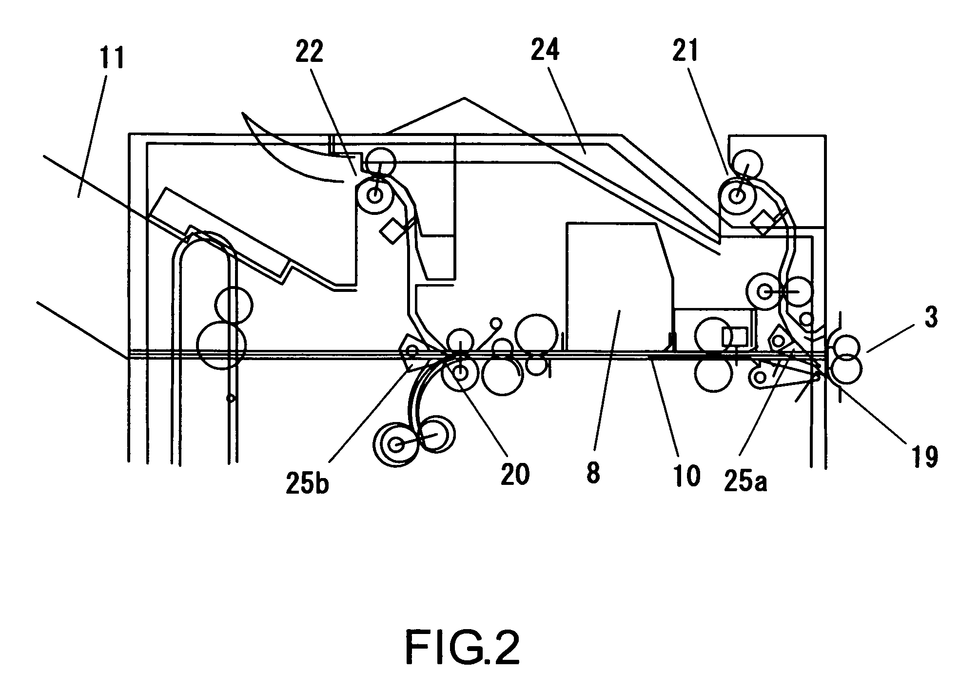
[0019]According to this configuration, the first introducing port for introducing sheets not larger than the predetermined size is provided at the lower part of the processing tray and a second introducing port for introducing sheets larger than a predetermined size provided at the upper part of the processing tray, whereby large size sheets can be piled from top of the processing tray and small size sheets can be piled from lower part of the processing tray along the tray surface in a good order and therefore there is no possibility that subsequent sheets are slipped in under the previously piled sheets.
[0021]According to this configuration, the sheet feeding path before the first introducing port is branched into the main feeding path and the branched feeding path, and, when a plurality of bundles of the sheets of the predetermined size are continuously processed on the processing tray, a first sheet of each bundle subsequent to a first bundle is kept waiting in the main feeding path and then piled onto the processing tray simultaneously with a second sheet of the each bundle that is introduced via the branched feeding path. By this, process of the previous bundle of the sheets is completed during waiting of the first sheet and therefore processing waiting time in the case of continuous processing can be eliminated, and post-processing efficiency of an A4 size sheet especially required for speed up can be enhanced.

Problems solved by technology

However, post-processing operation has been inefficient due to the processing waiting time in the sheet post-processing apparatus.
Therefore, the introducing port 4 needs to be moved depending on the sheet size; however, this separately requires a driving system for moving the introducing port 4, thereby making the configuration of the device complicated, as well as resulting in increased size and cost of the device.
However, in the case where both the end-binding process and middle-binding process are performed on the processing tray 2, introducing paths for sheets are complicated and easy to generate a jam on the processing tray 2.
Still, generally, the bundle of the sheets performed by middle-binding is simultaneously performed by middle-folding process to be in a brochure form and therefore a middle-folding device is required to be provided adjacent to the processing tray 2; however, it is difficult to secure a sufficient arrangement space.
Further, the number of capable of binding of a separated type stapler is less compared to that of an integrated stapler and therefore, in the case where an exclusive color printing paper whose paper surface is hard due to especially surface finishing is used, a stapling process cannot be performed by the number of capable of processing guaranteed in the case of a plain paper and it is difficult to perform both middle-binding and end-binding by the separated type stapler.
H06-99070 and Japanese Patent No. 2783326, waiting time for accepting sheets and loss of moving time of sheets and a stapler are resolved to accelerate processing, but the aforementioned problems have not been solved.
Furthermore, it may be taken into account that the number of capable of processing is increased using a large separated type stapler and an integrated stapler for end-binding is separately provided in addition to a separated type stapler; however, since arrangement space is limited in the vicinity of the processing tray 2, it is difficult to increase the stapler in size and to arrange two staplers.
Further, according to Japanese Unexamined Patent Application No. 11-263502, since a plurality of branching claws need to be provided for different sheet sizes and to be switched, there is a problem in that a structure of the feeding paths is complicated.

Method used


Image

  • Sheet post-processing apparatus
  • Sheet post-processing apparatus
  • Sheet post-processing apparatus

Examples


Embodiment Construction

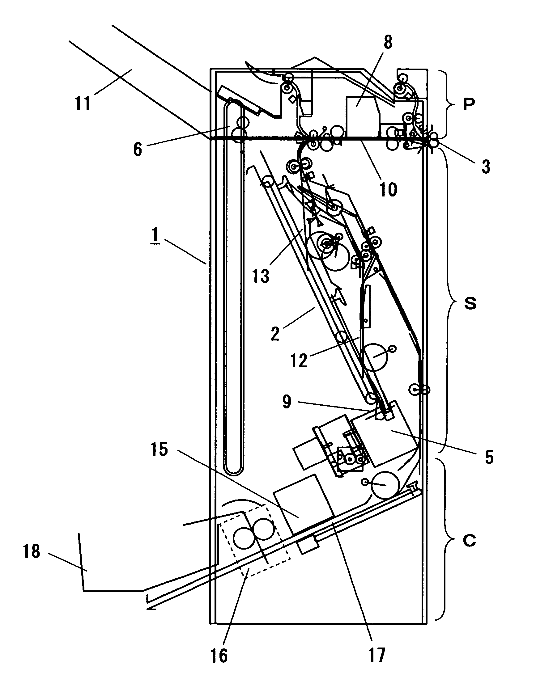
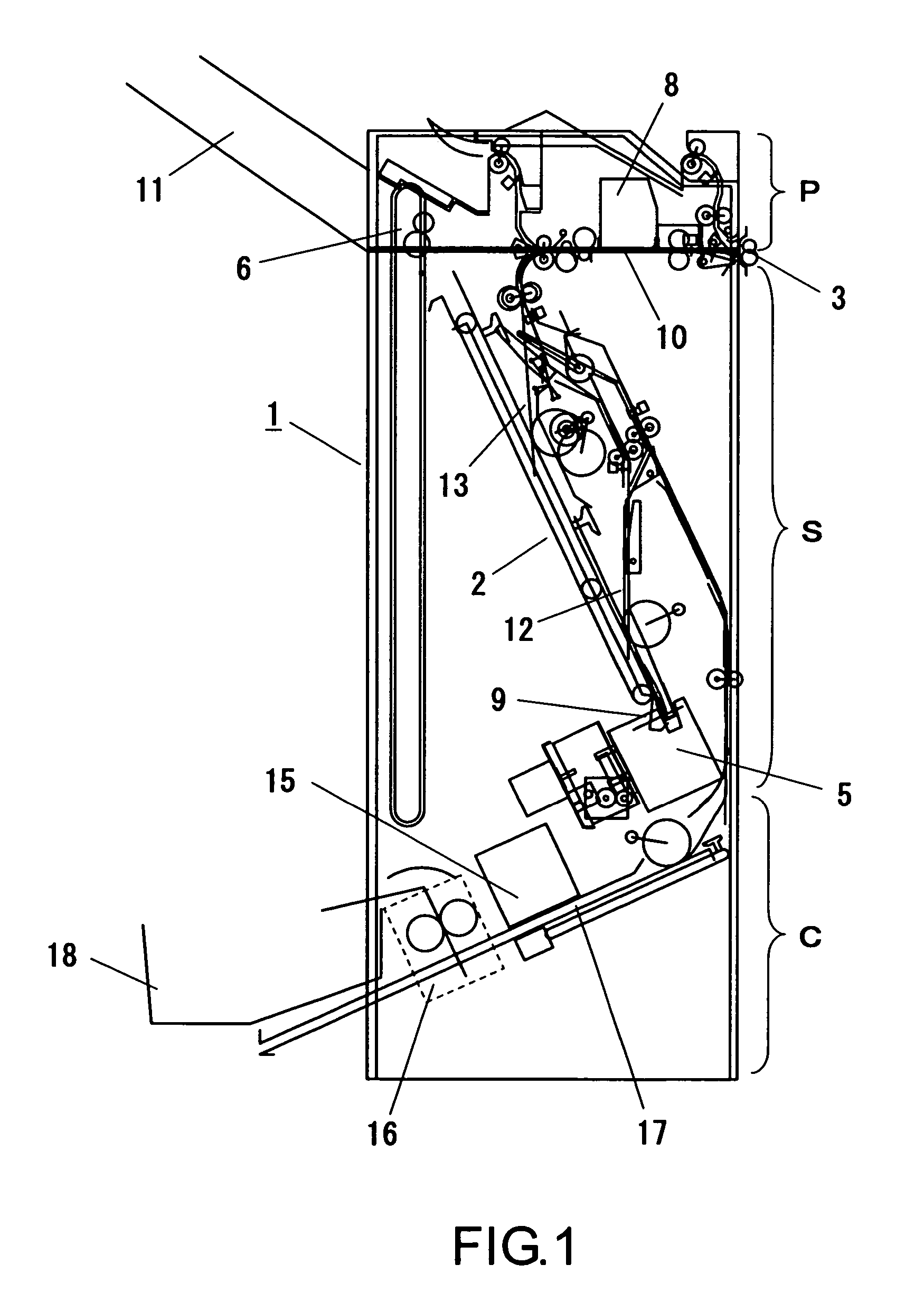
[0031]An embodiment of the present invention will be described below with reference to the drawings. FIG. 1 is a side sectional view showing configuration of a sheet post-processing apparatus according to the present invention. The sheet post-processing apparatus of the present invention includes a middle-binding and middle-folding unit which performs middle-binding and middle-folding of sheets in addition to an end-binding unit, and sheet feeding to the middle-binding and middle-folding unit is performed without via a processing tray.

[0032]In FIG. 1, a sheet post-processing apparatus 1 includes a punching unit P which forms a punch hole on a sheet, an end-binding unit S which aligns end portions of a bundle of sheets piled on a processing tray 2 and performs a stapling process, and a middle-binding and middle-folding unit C which performs the stapling process on the center of the sheet bundle and then folds centering around the stapling portion to be in a brochure form.

[0033]The pu...


PUM

PropertyMeasurementUnit
sizeaaaaaaaaaa
volumeaaaaaaaaaa
lengthaaaaaaaaaa

Abstract

A sheet post-processing apparatus (1) includes a punching unit (P), an end-binding unit (S) which aligns end portions of a sheet bundle piled on a processing tray (2) and performs a stapling process, and a middle-binding and middle-folding unit (C) which performs a stapling process on the center of the sheet bundle and then folds centering around the stapling portion to be in a brochure form. The middle-binding and middle-folding unit (C) is independently provided on the lower side of the end-binding unit (S) and a middle-binding and middle-folding feeding path (27) feeds sheets to the middle-binding and middle-folding unit (C) without via the processing tray (2) of the end-binding unit (S).

Description

BACKGROUND OF THE INVENTION[0001]This application is based on Japanese Patent Application No. 2004-345149 filed on Nov. 30, 2004.[0002]1. Field of the Invention[0003]The present invention relates to a sheet post-processing apparatus which performs a sheet sorting process, a sheet stapling process, or the like after image forming.[0004]2. Description of the Prior Art[0005]For example, there may be a case where a binding process (hereinafter referred to as a stapling process) and a holing process (hereinafter referred to as a punching process) are desired to be performed on a relatively large volume of sheets of paper bearing an image transferred thereon by an image forming apparatus such as a copying machine or a printer. In such a case, it is convenient to use a sheet post-processing apparatus or a so-called finisher that automatically performs a predetermined post-processing, such as a stapling process and a punching process.[0006]FIG. 7 is a side sectional view showing an example ...

Claims


Application Information

Patent Timeline
Patent Type & Authority Patents(United States)
IPC IPC(8): B65H37/04
CPCB42C1/12B65H45/18B65H2301/1635B65H2301/164B65H2301/4505B65H2405/20B65H2511/10B65H2511/414B65H2513/42B65H2220/01B65H2220/02B65H2701/1829
Inventor TAGUCHI, TETSUYATAKEMOTO, MITSUTOSHIMATSUO, TAKESHIMIYAZAKI, MASAHIKOEGAWA, KEISUKE
Owner KYOCERA DOCUMENT SOLUTIONS INC
Why Eureka
Eureka Blog
Learn More