Eureka AIR delivers breakthrough ideas for toughest innovation challenges, trusted by R&D personnel around the world.

System and method for detecting processing speed of integrated circuit

a technology of integrated circuits and detection systems, applied in pulse manipulation, pulse techniques, instruments, etc., can solve the problems of increasing the cost of the test platform, reducing the overall cost and power consumption of the test unit b>12/b>, and reducing the complexity of the design. the effect of production cost and power consumption

Inactive Publication Date: 2007-03-15
SILICON INTEGRATED SYSTEMS
View PDF2 Cites 5 Cited by
  • Summary
  • Abstract
  • Description
  • Claims
  • Application Information

AI Technical Summary

Benefits of technology

[0009] Hence, an object of the invention is to provide a detection system and method capable of accurately detecting the processing speed of an integral circuit (IC) in an efficient way where the design complexity, production cost, and power consumption are all reduced.
[0012] Through the design of the invention, since the detection system of the invention requires only one flip-flop, and a clock signal rather than a high-frequency signal is used for the speed detection, the design complexity, production cost, and power consumption are all reduced.

Problems solved by technology

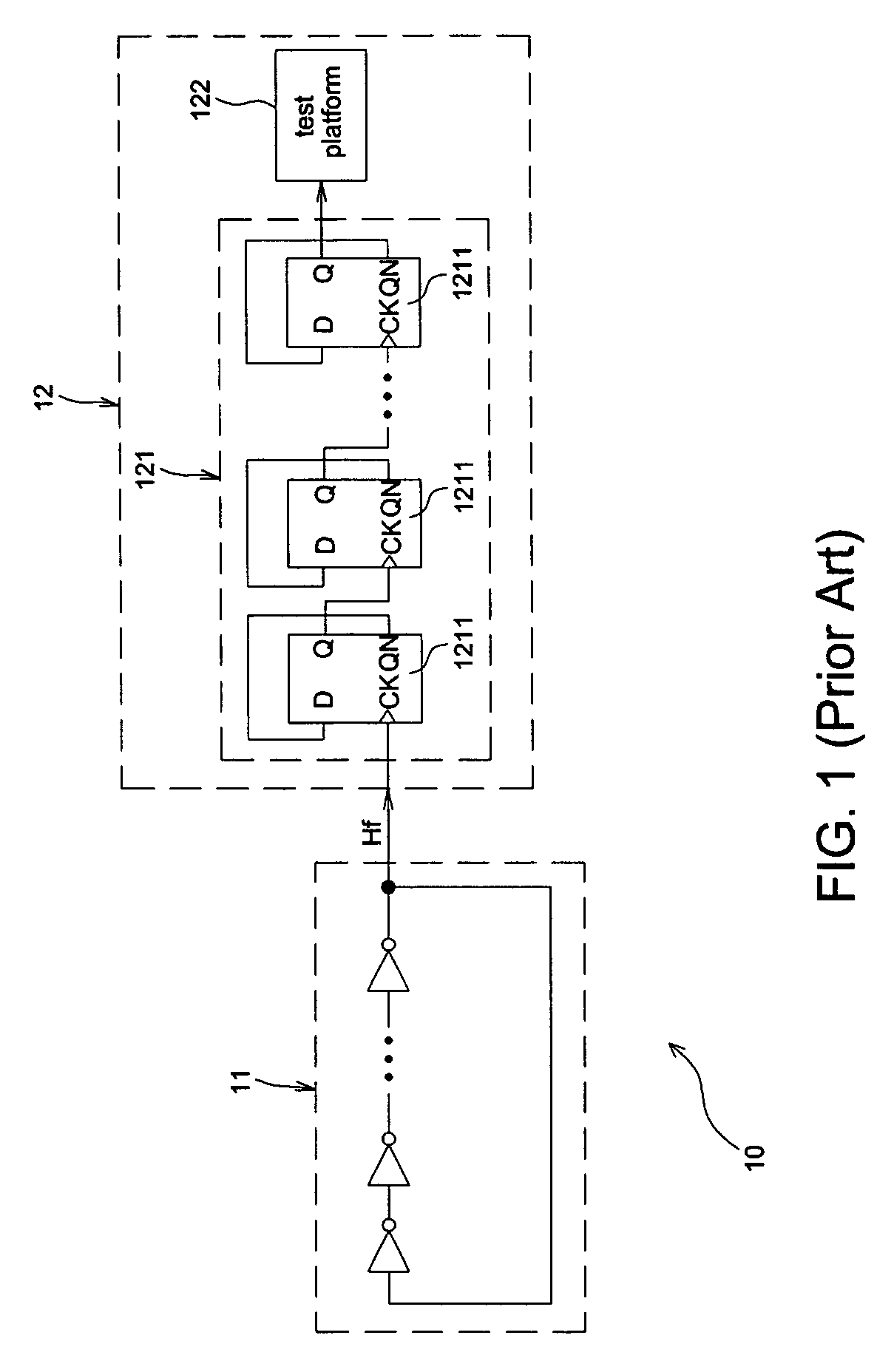
Further, since the test platform becomes more expensive as a broader detecting frequency range is provided, the cost of the test platform is reduced when the frequency of the oscillation frequency signal Hf is lowered.
However, it is clearly seen that the overall cost and power consumption of the test unit 12 are elevated as the number of the frequency eliminators 1211 is increased.
Besides, in case the numerous frequency eliminators 1211 are built inside an IC, the occupied space of an IC will inevitably expand.
On the other hand, the ring oscillator 11 and the external test unit 12 that operate at a high frequency may also result in high power consumption.

Method used


Image

  • System and method for detecting processing speed of integrated circuit
  • System and method for detecting processing speed of integrated circuit
  • System and method for detecting processing speed of integrated circuit

Examples


Embodiment Construction

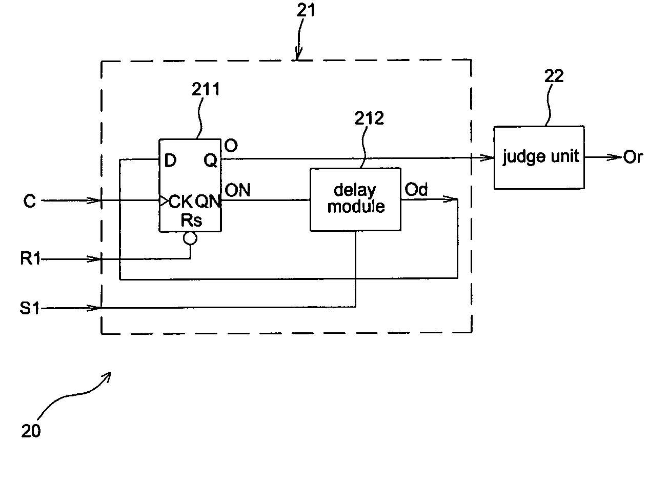
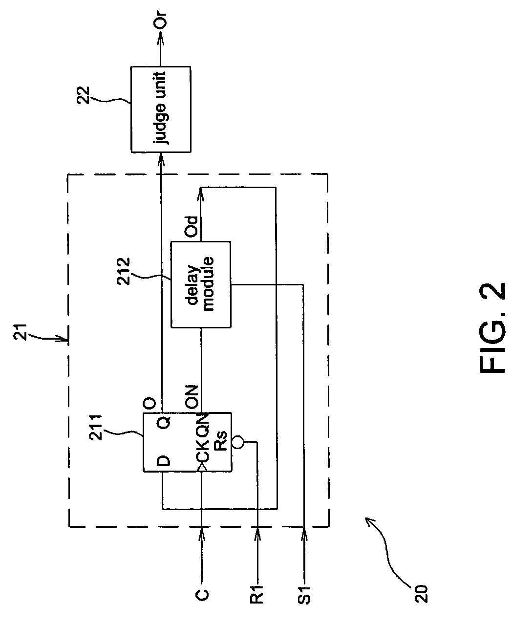
[0026]FIG. 2 shows a schematic diagram illustrating a detection system 20 of the invention for detecting the processing speed of an IC. The detection system 20 includes a clock output device 21 and a judge unit 22. The clock output device 21 of this embodiment is built inside the IC and used for outputting a signal in positive correlation to the processing speed. The judge unit 22 checks the clock status of the signal to detect the processing speed of the IC. Note that the judge unit 22 of the invention can be easily built inside the IC for its simplified and compact design.

[0027] The clock output device 21 of this embodiment includes a flip-flop 211 and a delay module 212. The flip-flop 211 includes an input port D, a timing port CK, an output port Q, an inverted output port QN, and a reset port RS. In this embodiment, the timing port CK is a falling-edge trigger port. Alternatively, the timing port CK may be a rising-edge trigger port. The reset port RS receives a reset signal R1...


PUM


Abstract

A system for detecting the processing speed of an integrated circuit (IC) includes a flip-flop, a delay module, and a judge unit. The flip-flop receives a clock signal as a trigger signal and generates an inverted output signal. The delay module receives the inverted output signal, adjusts the delay time of the inverted output signal according to a selection signal, and outputs a delay signal to the flip-flop to have the flip-fop generate the output signal. The judge unit receives the output signal and generates a judge signal, which is enabled when the clock period of the output signal is longer than that of the clock signal.

Description

BACKGROUND OF THE INVENTION [0001] (a) Field of the Invention [0002] The invention relates to a detection system and method and, more particularly, to a detection system and method capable of detecting the processing speed of an integral circuit (IC). [0003] (b) Description of the Related Art [0004] Typically, each IC product may tend to have a different processing speed due to different factors, e.g. the situation of the environment, the stability of temperature, etc, during the manufacturing processes. However, since all IC products in the same batch must have the same processing speed that conform to a specific specification, they must be ranked according to their respective processing speeds, and then speed compensation is made thereon to allow all IC products in the same batch to have identical processing speeds. [0005]FIG. 1 shows a conventional detection system for detecting the processing speed of an IC. The detection system 10 includes a ring oscillator 11 built inside the ...

Claims


Application Information

Patent Timeline
Patent Type & Authority Applications(United States)
IPC IPC(8): H03H11/26
CPCG01R31/3016G01R31/31703H03K2005/00058H03H11/265G01R31/31725
Inventor YEH, YING JYHFANG, CHUNG YIN
Owner SILICON INTEGRATED SYSTEMS
Why Eureka
Eureka Blog
Learn More