Liquid crystal display

a liquid crystal display and display technology, applied in non-linear optics, instruments, optics, etc., can solve the problems of increasing the power consumption of the liquid crystal display, requiring a large change in the manufacturing process, etc., and achieve the effect of improving the brightness efficiency of electric power

Inactive Publication Date: 2007-03-15
HITACHI DISPLAYS
View PDF7 Cites 11 Cited by
  • Summary
  • Abstract
  • Description
  • Claims
  • Application Information

AI Technical Summary

Benefits of technology

[0019] A liquid crystal display according to the present invention greatly improves the brightness efficiency of electric power, a color specification range and a contrast ratio, by specifying the configuration of a lighting unit, a reflective polarizer, a polarizing plate and a liquid crystal layer, a light source of the lighting unit, a reflection spectrum of the reflective polarizer and a transmission spectrum of the liquid crystal display portion.

Problems solved by technology

However, any of these means increases a power consumption of a liquid crystal display, and requires a large change for a manufacturing process.
A problem to be solved is to simultaneously realize the expansion of a color specification range, increase in a contrast ratio and the reduction of power consumption by simple means.

Method used


Image

  • Liquid crystal display
  • Liquid crystal display
  • Liquid crystal display

Examples


embodiment 1

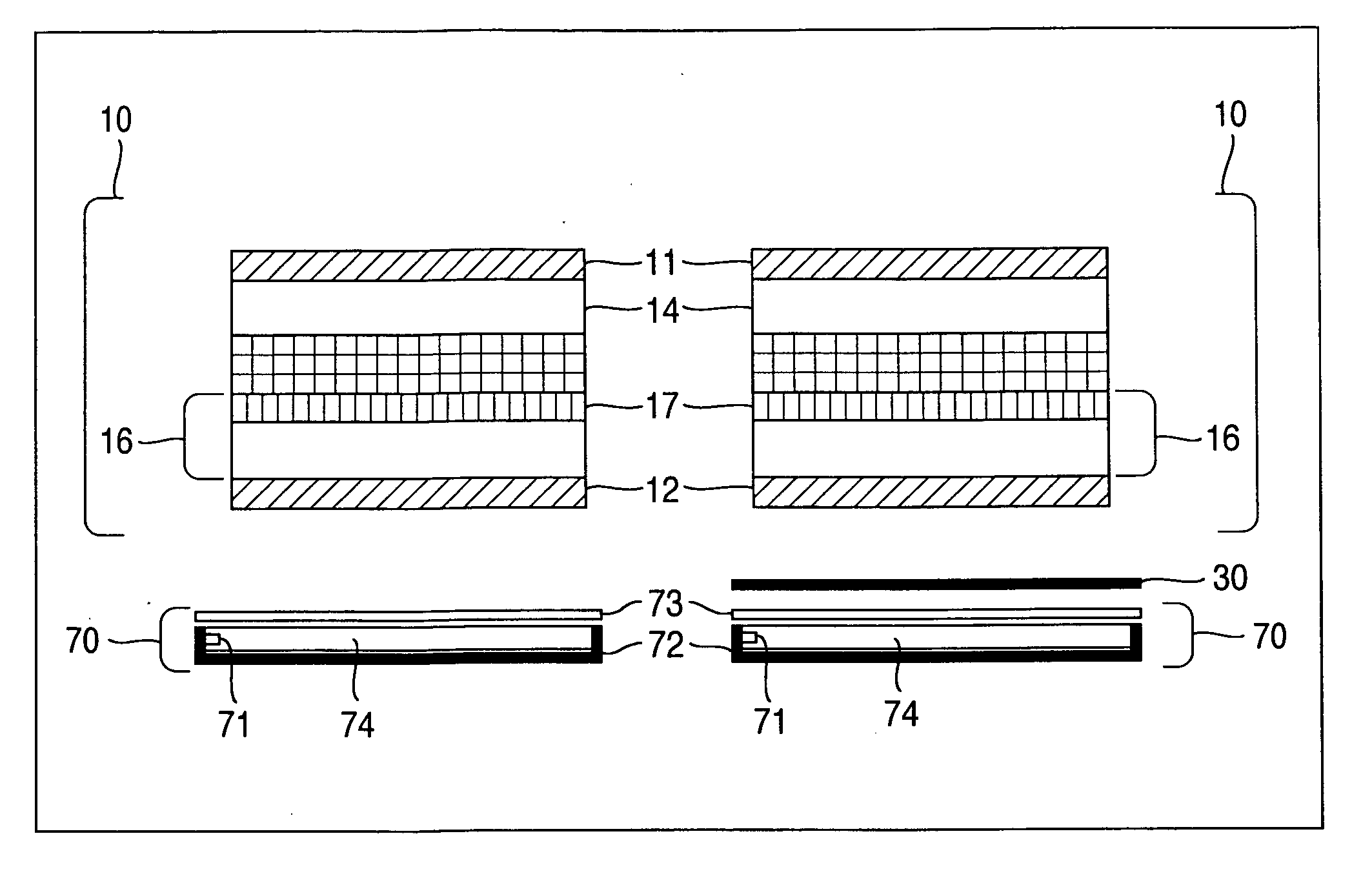
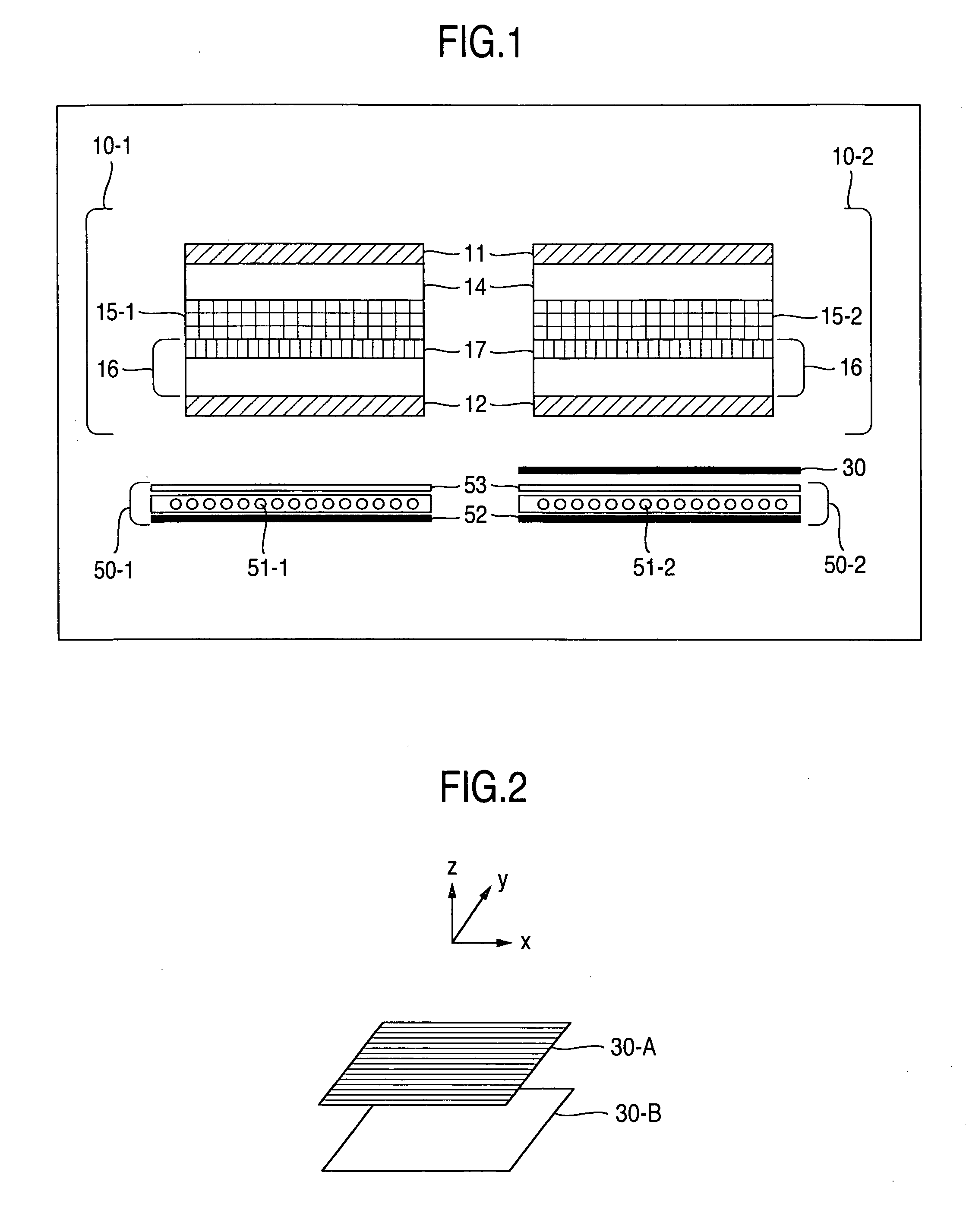
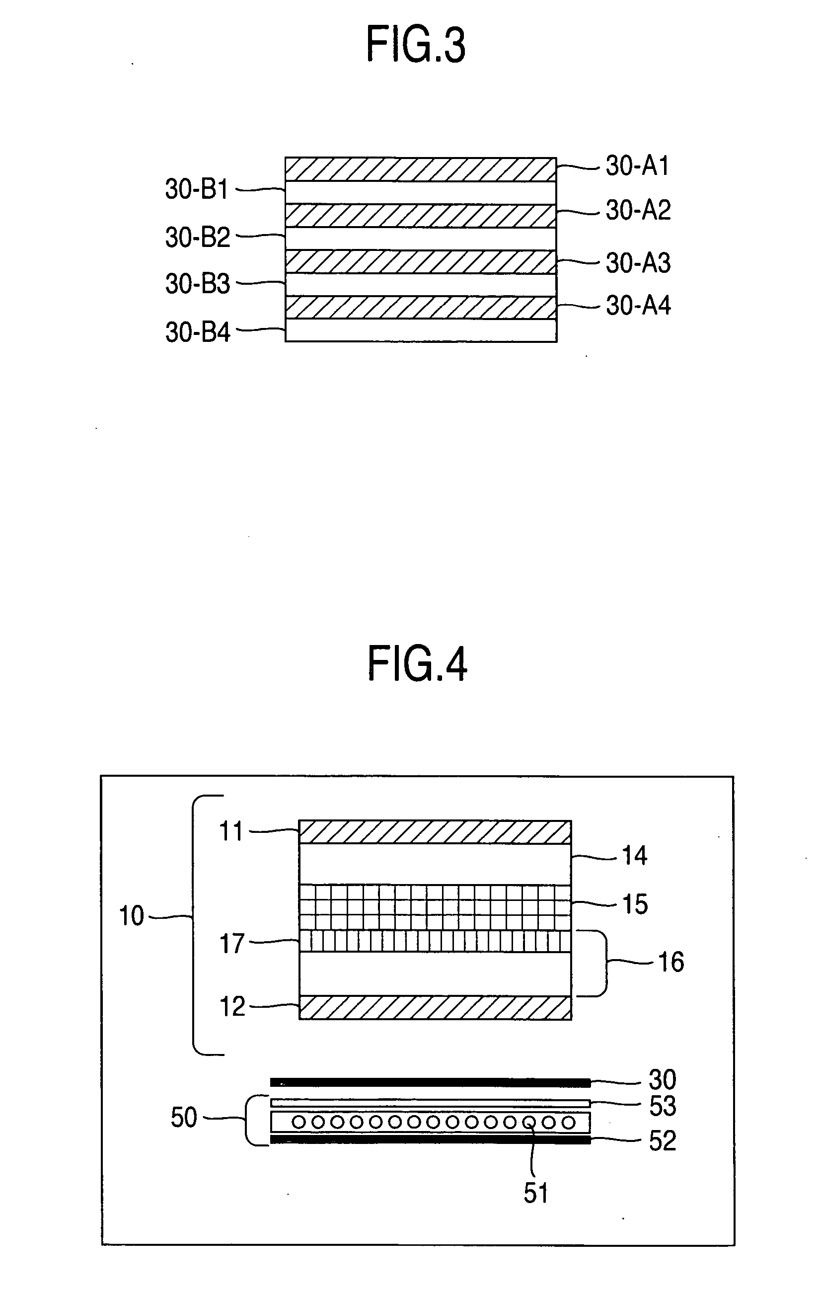
[0068] A structure of the liquid crystal display according to the present embodiment is shown in the right side of FIG. 1. The left side of FIG. 1 shows a general liquid crystal display as a comparative object. A reflective polarizer 30 shows the maximum reflectance at a wavelength of about 450 nm as is shown in FIG. 12. The reflective polarizer was obtained by preparing birefringent films 30-A having a refractive index of 1.6 for an extraordinary ray and a film thickness of 70 nm, and isotropic layers having a refractive index of 1.5 and a film thickness of about 70 nm, and stacking about 20 layers of them respectively so as form a configuration, for instance, of the reflective polarizer in FIG. 3. FIG. 13 shows a result of having compared emission spectra between backlight units, in which (1) shows an emission spectrum of a backlight unit 50-1, and (2) shows an emission spectrum of a backlight unit 50-2. As is understood from the figure, the lighting unit according to the present ...

embodiment 2

[0069] A structure of the liquid crystal display according to the present embodiment is shown in the right side of FIG. 1. The left side of FIG. 1 shows a general liquid crystal display as a comparative object. A reflective polarizer 30 showed the maximum reflectance at a wavelength of about 450 nm as is shown in FIG. 12. FIG. 14 shows a result of having compared emission spectra between backlight units, in which (1) shows an emission spectrum of a backlight unit 50-1, and (2) shows an emission spectrum of a backlight unit 50-2. In addition, liquid crystal layers 15-1 and 15-2 were the same type as an IPS mode described in JP-A-2001-056476, and were formed so as to show the retardation of respectively 350 nm and 440 nm. As a result, the liquid crystal display according to the present invention showed a contrast ratio increased by 10% and brightness in displaying white also increased by 10%, while keeping a color temperature in displaying white and power consumption approximately equ...

embodiment 3

[0070] A structure of the liquid crystal display according to the present embodiment is shown in the right side of FIG. 1. The left side of FIG. 1 shows a general liquid crystal display as a comparative object. The reflective polarizer 30 showed the maximum reflectance at a wavelength of about 660 nm as is shown in FIG. 15. The reflective polarizer was obtained by preparing birefringent films 30-A having a refractive index of 1.6 for an extraordinary ray and a film thickness of 105 nm, and isotropic layers having a refractive index of 1.5 and a film thickness of about 105 nm, and stacking about 20 layers of them respectively so as form a configuration, for instance, of the reflective polarizer in FIG. 3.

[0071]FIG. 16 shows a result of having compared emission spectra between backlight units, in which (1) shows an emission spectrum of a backlight unit 50-1, and (2) shows an emission spectrum of a backlight unit 50-2. As is understood from the figure, a cold cathode fluorescent tube ...


PUM

PropertyMeasurementUnit
wavelengthsaaaaaaaaaa
wavelength λ2aaaaaaaaaa

Abstract

A liquid crystal display has a liquid crystal panel having a liquid crystal layer sandwiched by a pair of substrates, and a backlight unit, wherein a reflective polarizer is arranged between a first substrate and the backlight unit; when λ0 [nm] is defined as a wavelength at which a spectral reflectance R of the reflective polarizer shows the maximum value, the reflective polarizer has such a wavelength λ0 [nm] that the following value R1 obtained by integrating the spectral reflectance with respect to a wavelength λ [nm] between λ0−50 [nm] and λ0+50 [nm]:
R1=∫λ0−50λ0+50Rdλ
and the following value R2 obtained by integrating the spectral reflectance with respect to wavelengths between 400 nm and 700 nm:
R2=∫400700Rdλ
satisfy the relation of R1/R2>0.4; and the reflective polarizer has a reflection axis in approximately parallel to an absorption axis of a first polarizing plate consumption to greatly improve all the performances, with a simple configuration.

Description

BACKGROUND OF THE INVENTION [0001] 1. Field of the Invention [0002] The present invention relates to a liquid crystal display, and particularly to a liquid crystal display which greatly improves a brightness efficiency of electric power, a color specification range and a contrast ratio. [0003] 2. Description of Related Art [0004] A technology on a liquid crystal display has remarkably progressed in recent years, and has been already widely practically used in an oversize TV for home use, a monitor for a personal computer, a personal digital assistant and the like. As the application field expands, needs for the enhancement of picture quality and lower power consumption further increase. [0005] Requirement for the improvement on the enhancement of picture quality includes the widening of an effective visual angle, increase in a contrast ratio and the expansion of a color specification range. [0006] For instance, as for the widening of an effective visual angle, a wide visual angle li...

Claims


Application Information

Patent Timeline
Patent Type & Authority Applications(United States)
IPC IPC(8): G02F1/1335
CPCG02F1/133533G02F1/1336G02F1/133536
Inventor KAJITA, DAISUKEUTSUMI, YUKAHIYAMA, IKUOISHII, MASAHIRO
Owner HITACHI DISPLAYS
Why Eureka
Try Eureka