
Method and apparatus for light recapture and sequential channel illumination

a light recapture and sequential channel technology, applied in the field of light recapture systems, can solve the problems of inconvenient use, inconvenient maintenance, and inability to meet the needs of color images, and achieve the effect of increasing brightness efficiency and high quality

Inactive Publication Date: 2009-12-24
DOLBY LAB LICENSING CORP
View PDF54 Cites 27 Cited by
  • Summary
  • Abstract
  • Description
  • Claims
  • Application Information

AI Technical Summary

Benefits of technology

[0014]The present inventor has realized the need to increase brightness efficiency in high quality multi-chip projectors, such as D-Cinema projectors, particularly when projecting multi-channel images such as 3D cinema or displays (e.g., rear projection televisions, front projectors, medical diagnostic display devices, etc).

Problems solved by technology

This method works best for black and white original images, and is not well suited for color images.
It has several problems, these include the need for a silver screen which is expensive, fragile, and not uniform.
Another problem is that the viewer must keep his head oriented vertically to avoid crosstalk from one eye to another.
Since having a direct wired connection to the Glasses in a theatre is impractical, a wireless or infrared signaling method is used to provide a timing reference for the left / right eye shuttering.
The single chip DLP projector described has a lack of efficiency which has been partially addressed through light recapture and the use of “scrolling color” across the DLP chip.

Method used


Image

  • Method and apparatus for light recapture and sequential channel illumination
  • Method and apparatus for light recapture and sequential channel illumination
  • Method and apparatus for light recapture and sequential channel illumination

Examples


Embodiment Construction

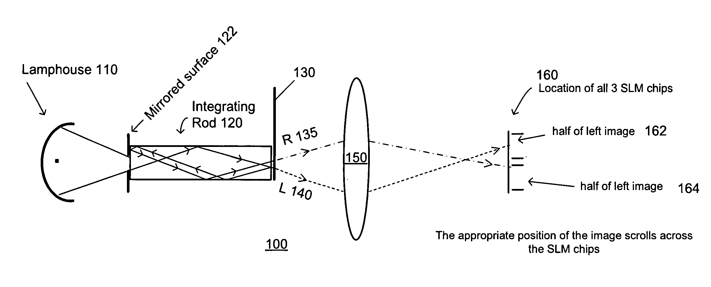
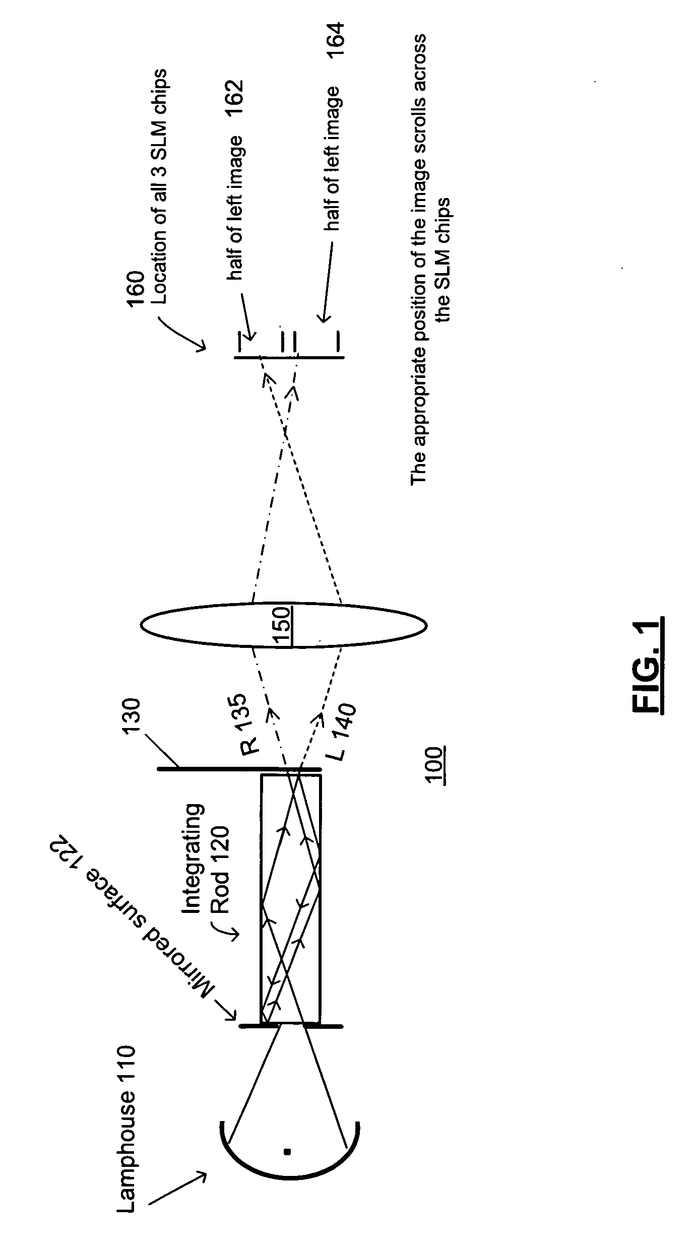
[0034]Referring now to the drawings, wherein like reference numerals designate identical or corresponding parts, and more particularly to FIG. 1 thereof, there is illustrated an optical schematic 100 according to an embodiment of the present invention. The schematic shows a light path from a lamphouse 110 to modulation chips 160 (e.g., 3 Spatial Light Modulator (SLM) Chips), which are, for example, TI DLP's, LCoS, or other modulators. An integrating rod 120 homogenizes light received from the lamphouse 110. A filter 130 (e.g., filter wheel) filters light exiting the integrating rod 120 into a light bundle with separate channels which are, for example, left and right channels of a 3D projection system. Optics 150 direct the filtered light so as to illuminate modulation surfaces of the modulation chips 160.

[0035]The filter 130 is located very close to the output of the integrating rod such that light reflected from the wheel re-enters the rod, and such that the wheel is located at an ...


PUM


Abstract

A filter wheel having spirally shaped left and right channel 3D filters. The 3D filters are, for example, spectral separation filters. The filter is mounted, for example, close to an integrating rod output of a projector. The left and right channel filtered light scrolls across a modulation device which is energized with correspondingly scrolling left and right image data. In one embodiment, the integrating rod comprises mirrored surfaces to facilitate recycling of light reflected off the filter wheel. The filter wheel may be placed in a single or dual projector configuration. In one embodiment, the filters are fixed at the end of an integrating rod using “re-cycled” light to illuminate different channels of a projection system.

Description

COPYRIGHT NOTICE[0001]A portion of the disclosure of this patent document contains material which is subject to copyright protection. The copyright owner has no objection to the facsimile reproduction by anyone of the patent document or the patent disclosure, as it appears in the Patent and Trademark Office patent file or records, but otherwise reserves all copyright rights whatsoever.BACKGROUND OF THE INVENTION[0002]1. Field of Invention[0003]The present invention relates to light recapture systems and particularly to light recapture in projection systems.[0004]2. Description of the Related Art[0005]Various methods are in place for 3D stereoscopic projection, including Anaglyph, Linear Polarization, Circular Polarization, Shutter Glasses, and Spectral Separation. Anaglyph is the oldest technology, and provides left / right eye separation by filtering the light through a two color filter, commonly red for one eye, and cyan for the other eye. At the projector, the left eye image is (co...

Claims


Application Information

Patent Timeline
Patent Type & Authority Applications(United States)
IPC IPC(8): G02B27/22G02B5/20G03B21/28H04N13/363
CPCG02B26/008G02B27/0994G03B35/16G03B35/26G03B21/206H04N13/0459G03B21/208H04N9/3111H04N13/0431H04N13/334H04N13/363
Inventor RICHARDS, MARTIN
Owner DOLBY LAB LICENSING CORP
Learn More