Image forming apparatus

a technology of image forming apparatus and forming tube, which is applied in the direction of power conversion system, dc-dc conversion, instruments, etc., can solve the problems of requiring a user to wait for a long time, excessive cost of an apparatus, interconnection of large current, and temperature drop, so as to reduce the cost and the size of an image forming apparatus, the effect of reducing cost and siz

Inactive Publication Date: 2007-03-15
RICOH KK
View PDF26 Cites 39 Cited by
  • Summary
  • Abstract
  • Description
  • Claims
  • Application Information

AI Technical Summary

Benefits of technology

[0023] According to one aspect of the present invention, the output of a power supply generation circuit can be used as a power supply of an external apparatus when required by the external apparatus, and the power supply generation part can be used as a charger in the case of charging a capacitor. As a result, it is possible to charge the capacitor without the need for a dedicated charger. Accordingly, it is possible to reduce the cost and the size of an image forming apparatus.
[0024] Thus, according to the present invention, it is possible to provide an image forming apparatus that can be reduced in cost and size.

Problems solved by technology

Therefore, at the time of use, the heating roller requires a long rise time of a few to tens of minutes before rising to a usable temperature of approximately 180° C., thus requiring a user to wait for a long time.
However, this is not desirable because if the commercial power supply is around 100 V, excessive cost is required for an apparatus and interconnections for applying large current.
However, decreasing the heat capacity of the heating roller causes a drop in the temperature of the heating roller in the case of successively forming images, thus producing a waiting period every time a predetermined number of copies are printed.
Accordingly, extra energy unnecessary for image forming is consumed in the standby period in which the image forming apparatus is not in use.
Further, there is also the phenomenon of capacity reduction due to the memory effect.
Accordingly, this technique is not sufficient to be used as the image forming apparatus.
However, an image forming apparatus using the capacitor disclosed in Patent Document 2 requires a dedicated charger separately from the capacitor, thus being higher in cost and larger in installation space.

Method used


Image

  • Image forming apparatus
  • Image forming apparatus
  • Image forming apparatus

Examples


first embodiment

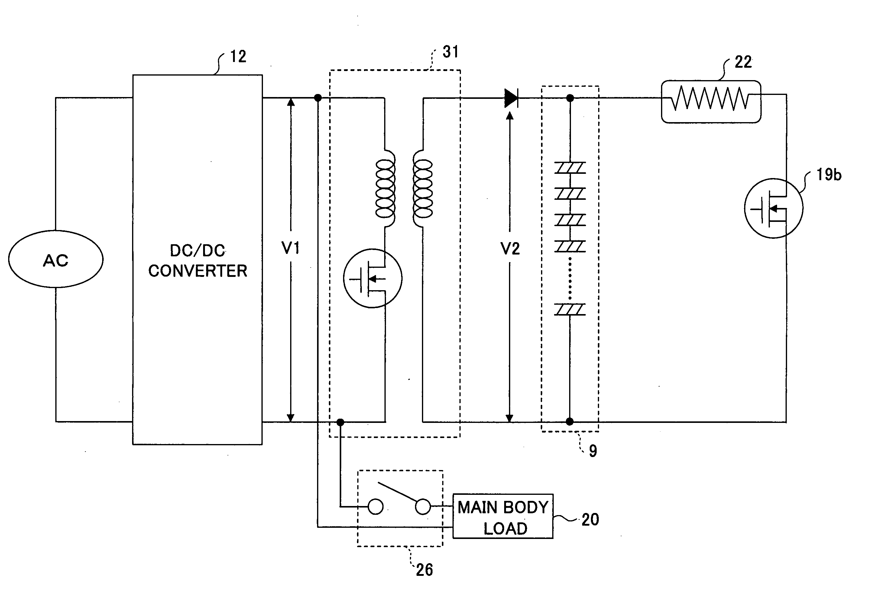
[0142]FIG. 3 is a schematic circuit diagram showing a power storage unit according to a first embodiment. According to the power storage unit of FIG. 3, an AC commercial power supply is connected to a DC / DC converter 12 after being subjected to rectification, and the output of the DC / DC converter 12 is connected to a main body load 20 and a charging part 31 of an image forming apparatus. The charging part 31 includes a high-frequency transformer 3 (FIG. 4). The charging part 31 increases the voltage V1 of the DC / DC converter 12 to a voltage V2, and charges a capacitor bank 9 with the voltage V2. The stored power (energy) is supplied to the fixing heater 22 by a temperature increase FET control buffer circuit 19b in accordance with the temperature of the DC fixing heater 22. Further, the DC / DC converter 12 and the main body load 20 are connected through a make-and-break (opening and closing) circuit 26. In the case of performing an image forming operation, the make-and-break circuit ...

second embodiment

[0224]FIG. 9 is a schematic circuit diagram showing a power storage unit according to a second embodiment. In FIG. 9, the same elements as those of FIG. 3 are referred to by the same reference numerals, and a description thereof is omitted. The power storage unit of this embodiment is different from that of the first embodiment in that power is supplied from the DC / DC converter 12 to the main body load 20 without going through the make-and-break circuit 26. In the case of performing an image forming operation, the main body load 20 performs the image formation using the power supplied from the DC / DC converter 12. At this point, if the temperature of the fixing heater 22 is lower than a predetermined value, the capacitor bank 9 is discharged so as to supply power to the fixing heater 22. Further, if no image forming operation is being performed, it is possible to charge the capacitor bank 9. A detailed description is given below, but a description of the same part as the first embodi...

third embodiment

[0255]FIG. 13 is a schematic circuit diagram showing a power storage unit according to a third embodiment. In FIG. 13, the same elements as those of FIG. 3 are referred to by the same reference numerals.

[0256] According to the power storage unit of FIG. 13, an AC commercial power supply is connected to the DC / DC converter 12 after being subjected to rectification, and the output of the DC / DC converter 12 is connected to the main body load 20. The DC / DC converter 12 and the charging part 31 are connected through a make-and-break (opening and closing) circuit 400.

[0257] The charging part 31 includes a boost chopper circuit 300 (FIG. 14). The charging part 31 increases the voltage V1 of the DC / DC converter 12 to a voltage V2, and charges the capacitor bank 9 with the voltage V2. The stored power (energy) is supplied to the fixing heater 22 by the temperature increase FET control buffer circuit 19b in accordance with the temperature of the DC fixing heater 22.

[0258] In the case of pe...


PUM


Abstract

An image forming apparatus is disclosed that includes a power storage unit. The power storage unit includes a constant voltage generation part configured to generate a constant voltage from a commercial power supply, the constant voltage generation part being connected to an external apparatus operating by consuming power; a voltage increasing circuit configured to increase the constant voltage generated by the constant voltage generation part; a capacitor configured to store an electric charge supplied from the voltage increasing circuit; a circuit control part configured to control charging of the capacitor; and an output part configured to output power stored in the capacitor, the power having a voltage different from the constant voltage.

Description

BACKGROUND OF THE INVENTION [0001] 1. Field of the Invention [0002] The present invention relates generally to image forming apparatuses, and more particularly to an image forming apparatus including a power storage unit that supplies stored power to a heating part. [0003] 2. Description of the Related Art [0004] Image forming apparatuses such as copiers, printers, facsimile machines, and MFPs (MultiFunction Peripherals) have a process of fixing heated toner onto plain paper. Heat roller fixing is often employed as a fixing method because of the need for high speed and safety. According to heat roller fixing, a heating roller heated by a heating member such as a halogen heater and a pressure roller disposed opposite the heating roller are in press contact with each other. Plain paper is caused to pass between the heating roller and the pressure roller, so that an unfixed toner image is fixed on the plain paper by heat and pressure. [0005] Generally, the heating roller employs a roll...

Claims


Application Information

Patent Timeline
Patent Type & Authority Applications(United States)
IPC IPC(8): G03G15/00
CPCG03G15/80H02M3/33507H02M3/156
Inventor SATO, NAOKIKIKUCHI, HIDEONAKAYA, MASAHIDE
Owner RICOH KK
Why Eureka
Try Eureka