Ultraviolet light filtration apparatus

a filter apparatus and ultraviolet light technology, applied in lighting and heating apparatus, separation processes, heating types, etc., can solve the problems of reducing the efficiency of the recirculating air system operation, and achieve the effect of reducing the odor of typical indoors and increasing the uv's reactivity

Inactive Publication Date: 2007-03-15
WILLETTE CHRISTOPHER A
View PDF7 Cites 15 Cited by
  • Summary
  • Abstract
  • Description
  • Claims
  • Application Information

AI Technical Summary

Benefits of technology

[0010] This invention intends to improve upon the application of air filtration elements by providing a means to help maintain these elements through the use of germicidal ultraviolet light, which can prevent organic fouling from occurring and spreading. In addition, when the ultraviolet light element is applied to specially formulated air filtration elements designed to enhance the ultraviolet light reactivity, improved organic filtration efficiency can be achieved and improved indoor air quality can result.
[0011] By applying the present invention's ultraviolet light apparatus to either a specially designed “U reactive” filter element or standard readily available filter elements, enhancement to the air filtration process can be achieved. The application of the ultraviolet light apparatus to air filtration elements helps to immediately sterilize captured organic contaminants—preventing them from flourishing and spreading.
[0013] It also involves a germicidal ultraviolet light (UV) apparatus mounted within a specially designed filter element that is designed to fit within the standard filter access ports for re-circulating air systems such as those found in heating ventilating and air conditioning systems (HVAC). The UV apparatus is intended to be mounted within the filter area of these specially designed filter elements such that the ultraviolet light source can be positioned to project the ultraviolet light towards surfaces found within the filter area and the surrounding air stream and components found downstream of the filter in the HVAC system for the purpose of sterilization and maintenance of these areas. In addition, these specially designed filter elements shall contain a special tackified air filtration media such as that offered by Superior Fiber, Inc., designed to increase the reactivity of the UV light within the filter area. (See, also, U.S. Pat. No. 6,136,058). Plus, further enhancement to the filtration media can be achieved by applying an electrical charge to the filter media to increase its ability to attract airborne particulate. (See, e.g., U.S. Pat. No. 6,764,533). These surfaces are often times problematic areas that fester organic growth that can pose potential health problems and reduce the efficiency of operation of the re-circulating air system.
[0014] In addition, the present invention involves a safety interlock mechanism in combination with the UV apparatus to prevent accidental exposure to the ultraviolet light source. This safety interlock cuts power to the UV source of the UV apparatus when the filter element is removed from the filter housing of the re-circulating air system.
[0016] Finally, the present invention involves a method for the reduction of typical indoor odors through the combination of ultraviolet light spectrums emitted by the UV apparatus. The combination of UV spectrums produces a UV oxidative effect that increases the UV's reactivity with odors and other volatile organic compounds (VOC's).

Problems solved by technology

These surfaces are often times problematic areas that fester organic growth that can pose potential health problems and reduce the efficiency of operation of the re-circulating air system.

Method used


Image

  • Ultraviolet light filtration apparatus
  • Ultraviolet light filtration apparatus
  • Ultraviolet light filtration apparatus

Examples


Embodiment Construction

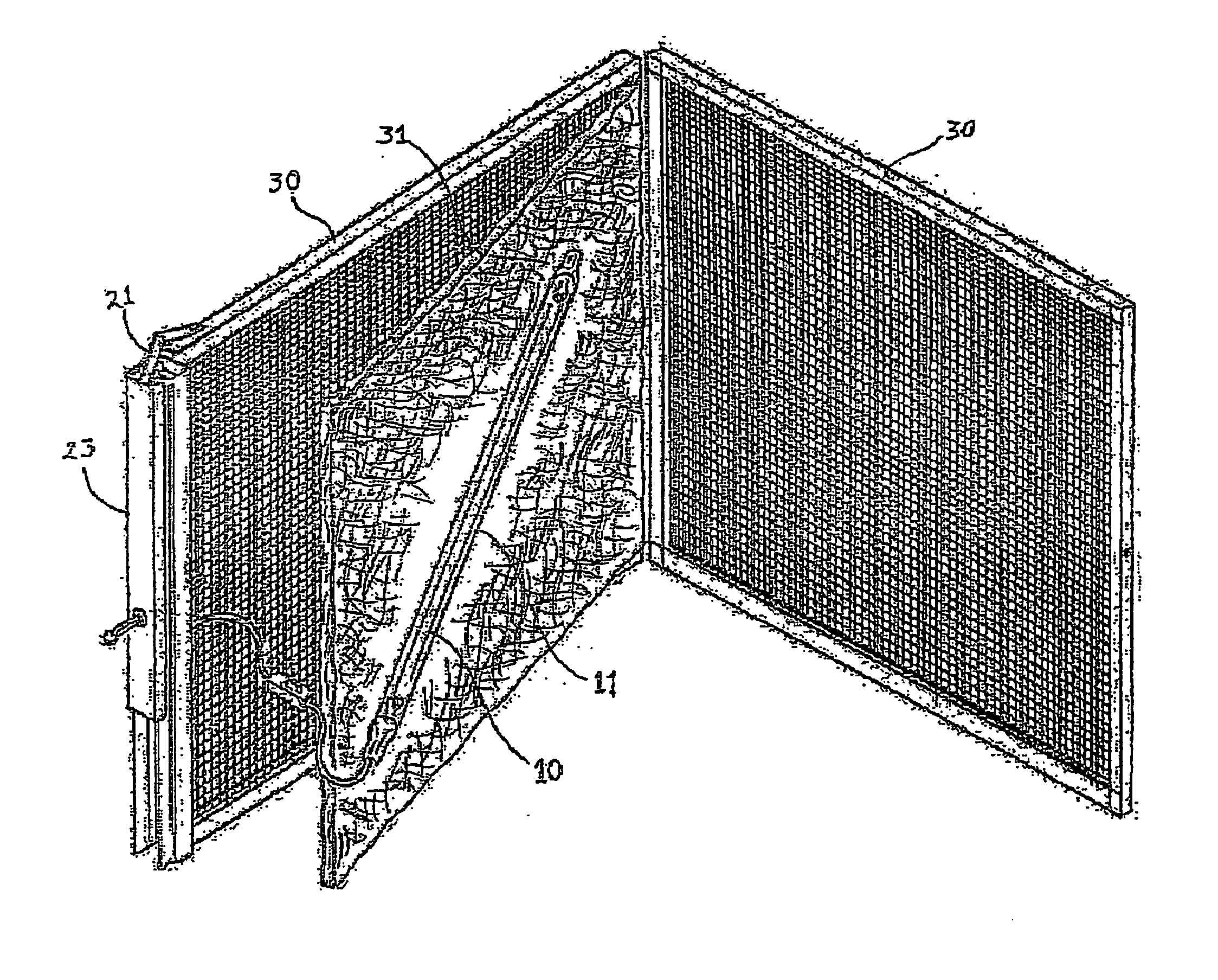
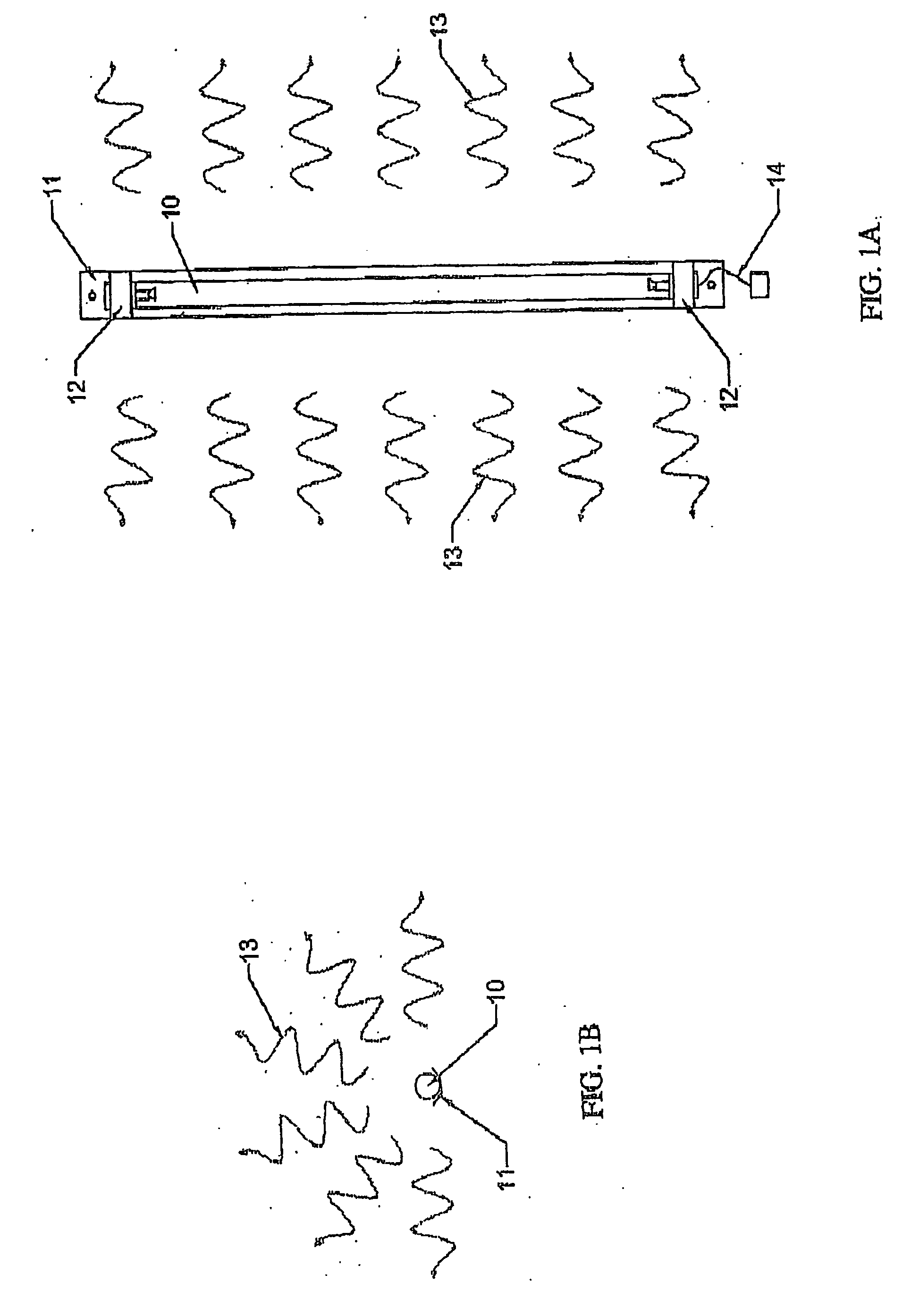
[0041]FIGS. 1A and 1B refer to the UV apparatus of my invention. This apparatus includes an ultraviolet light source 10, which is intended to generate germicidal ultraviolet light for the purpose of sterilization of organic contaminants. This UV light source 10 can include either a mercury vapor type of light source or light emitting diodes (LED's) with light energy's ranging in the ultraviolet light ranges of UVA, UVB or UVC with specific concentrations in the UVC germicidal band range. The germicidal band range is approximately 200-300 nm, with a peak germicidal effectiveness at approximately 254 nm. The germicidal process involves absorption of a UV photon in this range by microbial DNA chains. This causes a disruption of the DNA chain, such that when a cell undergoes mitosis (cell division), the replication of DNA is inhibited, and the cell is unable to reproduce (i.e., is sterilized). This process prevents further growth of cell colonies, such as mold, and eventually the colony...


PUM

PropertyMeasurementUnit
conductivityaaaaaaaaaa
poweraaaaaaaaaa
humidityaaaaaaaaaa

Abstract

In the present invention a germicidal ultraviolet light apparatus is mounted within a specially designed filter element that is designed to fit within the standard filter access ports for re-circulating (HVAC) air systems. The ultraviolet light source is positioned to project ultraviolet light towards surfaces found within the filter area and components found downstream of the filter in the HVAC system for the purpose of sterilization and maintenance of these areas. Preferably, the filter elements contain a special tackified air filtration media designed to increase the reactivity of the UV light within the filter area. In addition, the present invention includes a safety interlock mechanism that cuts power to the UV source when the filter element is removed from the re-circulating air system. Finally, the present invention involves various sources of supplying power to the UV apparatus for installation flexibility.

Description

REFERENCE TO RELATED APPLICATIONS [0001] This application claims an invention which was disclosed in Provisional Application No. 60 / 571,384, filed May 14, 2004, entitled “Ultraviolet Light Filtration Apparatus”. The benefit under 35 USC §119(e) of the United States provisional application is hereby claimed, and the aforementioned application is hereby incorporated herein by reference.BACKGROUND OF THE INVENTION [0002] 1. Field of the Invention [0003] The present invention relates to an ultraviolet light air filter apparatus for application into typical air filtration ports found in heating, ventilating and air conditioning (HVAC) systems. The device is intended for the reduction and control of organic contamination that can occur on the air filtration element and surrounding components within the re-circulating air system. [0004] 2. Description of Related Art [0005] Contaminants including particulates and organics contaminants such as algal, fungal, bacterial, and viral agents in re...

Claims


Application Information

Patent Timeline
Patent Type & Authority Applications(United States)
IPC IPC(8): B01J19/12A61L9/16A61L9/20B01D53/00B01J19/08F24F3/16F24F13/28
CPCA61L9/16A61L9/20B01D46/0028B01D46/4245B01D53/007F24F2003/1667B01D2259/804B01D2279/50F24F3/166F24F13/28B01D2257/90F24F8/192F24F8/22Y02A50/20
Inventor WILLETTE, CHRISTOPHER A.
Owner WILLETTE CHRISTOPHER A
Why Eureka
Try Eureka