System and method for optimizing a wireless connection between wireless devices

Inactive Publication Date: 2007-03-15
SYMBOL TECH INC
View PDF5 Cites 44 Cited by
  • Summary
  • Abstract
  • Description
  • Claims
  • Application Information

AI Technical Summary

Problems solved by technology

Thus, the association and authentication with each AP may cause a delay in the communication.
For many applications (e.g.,

Method used


Image

  • System and method for optimizing a wireless connection between wireless devices
  • System and method for optimizing a wireless connection between wireless devices
  • System and method for optimizing a wireless connection between wireless devices

Examples


Example

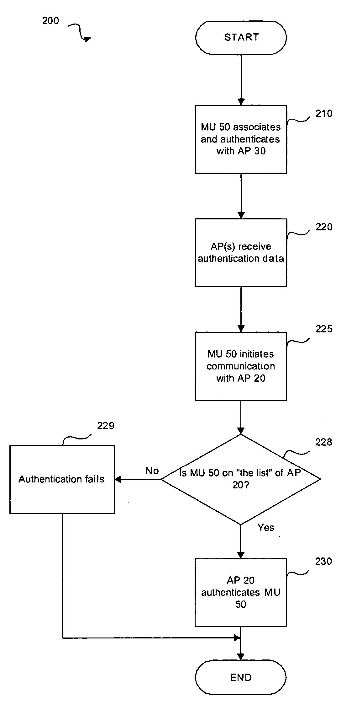
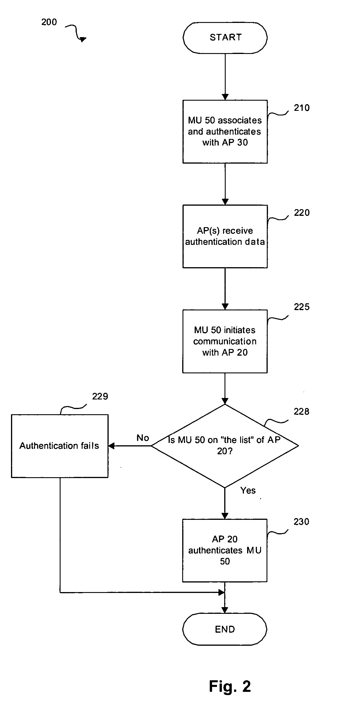
[0007] The present invention may be further understood with reference to the following description and the appended drawings, wherein like elements are provided with the same reference numerals. The present invention discloses a system and method for optimizing a wireless connection between wireless devices. Although the present invention may be described with reference to an IEEE 802.11 wireless network, those of skill in the art will understand that the present invention may be utilized with other types of network protocols and architectures.

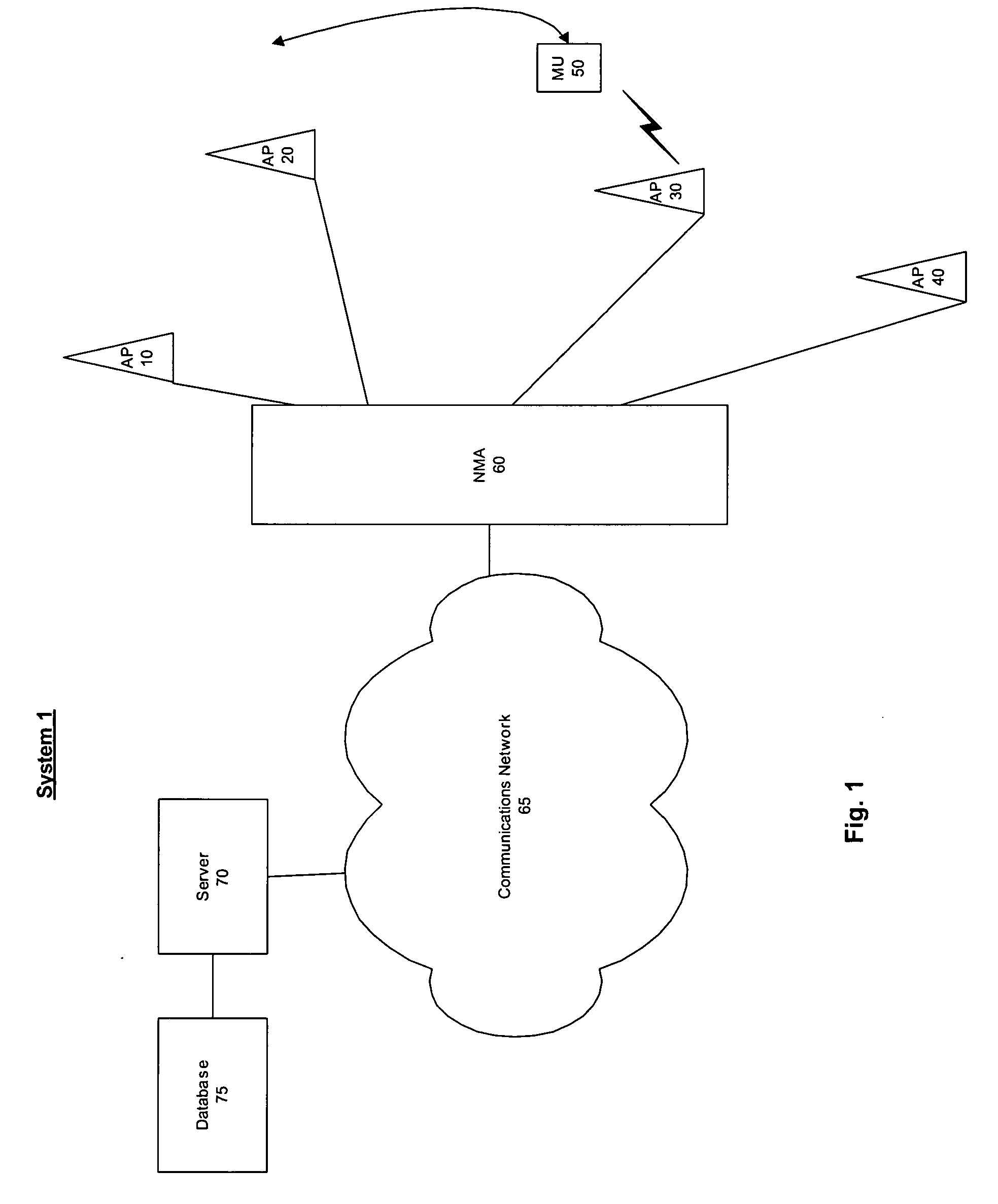
[0008]FIG. 1 shows an exemplary embodiment of a system 1 according to the present invention. The system 1 may include a WLAN comprising a network management arrangement (“NMA”) 60 coupled to access points (“APs”) 10, 20, 30, and 40. Each of the APs 10-40 may have a corresponding coverage area which defines a range over which the AP may transmit and receive a radio frequency (“RF”) signal. A mobile unit (“MU”) 50 located within a particular co...


PUM


Abstract

Described is a method where a wireless mobile unit (“MU”) transmits an association request and an authentication request to an access point (“AP”). The association request includes an identifier of the MU and the authentication request includes authentication data of the MU. An authentication procedure of the MU is performed as a function of the identifier and the authentication data. The AP adds the identifier and the authentication data to an authenticated list. Access to the list is provided to at least one further AP. When the at least one further AP receives a further association request including the identifier from the MU, the further AP performs a further authentication procedure as a function of the identifier and the list.

Description

BACKGROUND INFORMATION [0001] A conventional wireless network includes one or more access points (“APs”) allowing a user of a mobile unit (“MU”) to move freely within the network while maintaining a connection thereto. As the MU moves within the network, it may communicate with different APs as it moves to different locations. When the MU ceases communicating with a first AP and begins communicating with a second AP, it is commonly referred to as a roam. [0002] To initiate communication with the second AP, the MU may execute a roam procedure which was previously executed with the first AP. The roam procedure includes an association and an authentication of the MU with the second AP, and may be completed in approximately 200 milliseconds to 3 seconds. Thus, the association and authentication with each AP may cause a delay in the communication. For many applications (e.g., Voice over Internet Protocol (“VoIP”)), the delay may result in a termination of the connection of the MU to the ...

Claims


Application Information

Patent Timeline
IPC IPC(8): H04M3/16H04W12/06H04W36/08H04W60/04H04W84/12H04W92/20
CPCH04W12/06H04W92/20H04W84/12H04W60/04H04W12/069
Inventor BATTA, PUNEET
Owner SYMBOL TECH INC
Why Eureka
Try Eureka