Wire rope incorporating fluoropolymer fiber

a fluoropolymer fiber and wire rope technology, applied in the field of wire ropes, can solve the problems of abrasion and bending fatigue of wire ropes, lubricants, breakage, and need costly and time-consuming replacement, and achieve the effect of increasing the durability of wire ropes

Active Publication Date: 2007-03-22
WL GORE & ASSOC INC
View PDF39 Cites 25 Cited by
  • Summary
  • Abstract
  • Description
  • Claims
  • Application Information

AI Technical Summary

Benefits of technology

[0012] In another aspect, the invention provides a method of increasing durability of a wire rope comprising the step of incorporating at least one fluoropolymer fiber into the wire rope.

Problems solved by technology

The primary failure mechanisms for wire ropes are abrasion and bending fatigue.
Such lubricants, however, break down over time and require costly and time-consuming replacement.
Effective replenishment of lubricant is also a problematic process.
The use of these fibers to replace metal wire can come at the expense of weakening the rope and have not been put to widespread use because of insufficient durability improvements.
They are relatively complicated and expensive to prepare and are difficult to accurately position in forming the rope.
Wire ropes still suffer from inadequate durability.

Method used


Image

  • Wire rope incorporating fluoropolymer fiber
  • Wire rope incorporating fluoropolymer fiber
  • Wire rope incorporating fluoropolymer fiber

Examples


example 1

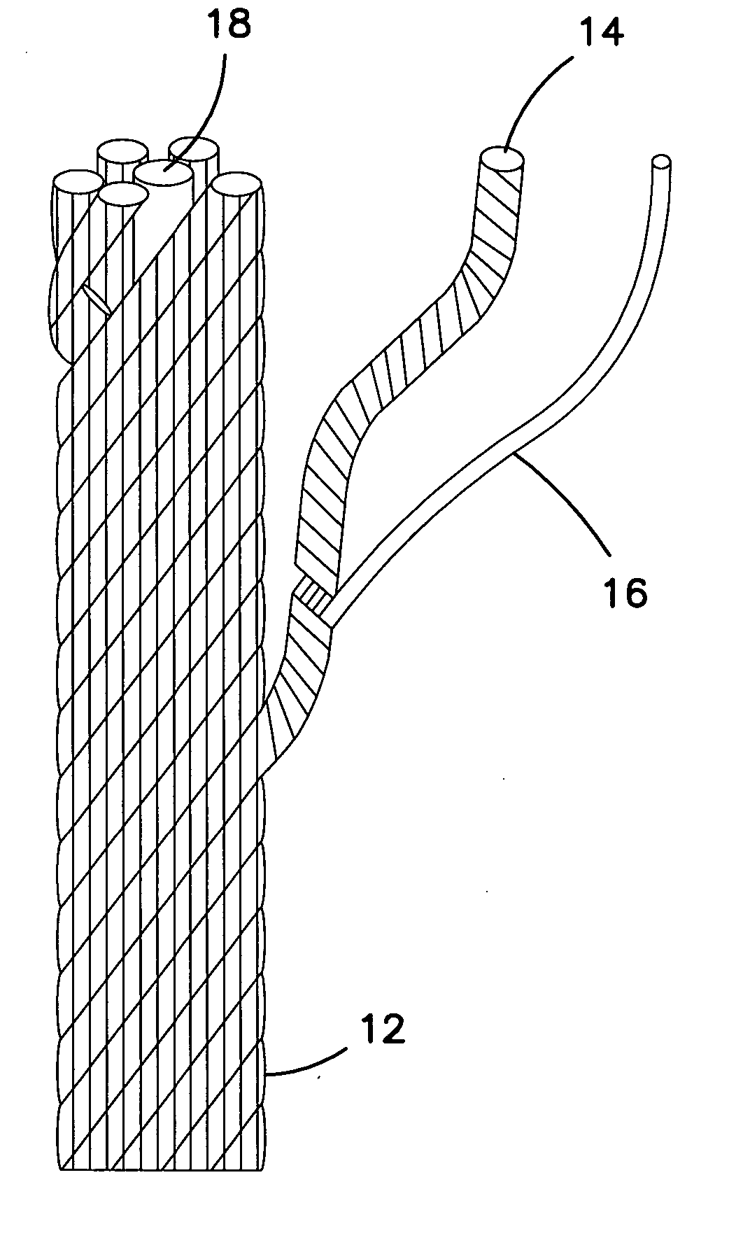
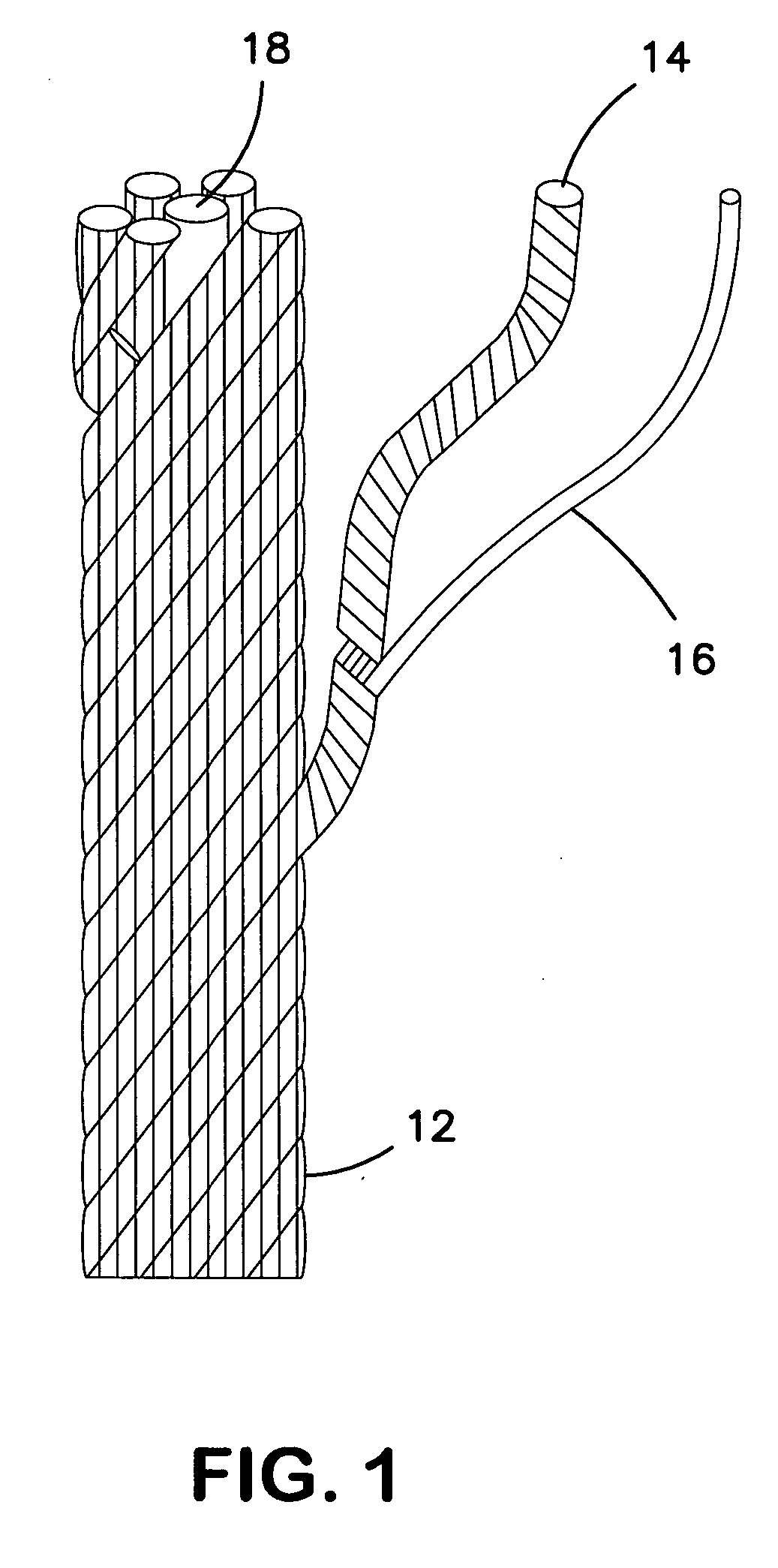
[0052] (a) Expanded PTFE monofilament fiber (part # V112447, W. L. Gore & Associates, Elkton Md.) was obtained. Properties of this fiber are presented in Table 1. The ePTFE fiber was combined with a single steel wire possessing a diameter of 0.32 mm, a mass per unit length of 5840 denier, and a break strength of 9.1 kg (Zinc Phos Braiding Wire 35, Techstrand, Lansing, Ill.). One of the fibers was combined with one of the wires. Fiber weight percent was determined. The two materials were twisted together and tested in accordance with the afore-mentioned abrasion test method. The test results appear in Table 2.

[0053] (b) Example 1(a) was repeated except two fibers were combined with one of the wires. Test results appear in Table 2.

[0054] (c) Example 1(a) was repeated except four fibers were combined with one of the wires. Test results appear in Table 2.

[0055] (d) Example 1(a) was repeated except six fibers were combined with one of the wires. Test results appear in Table 2.

[0056] ...

example 2

[0057] Expanded PTFE monofilament fiber was obtained that possessed the following properties: weight per unit length of 769 denier, tenacity of 2.4 g / d, and diameter of 0.29 mm. Properties of this fiber are presented in Table 1. The ePTFE fiber was combined a single steel wire possessing a diameter of 0.32 mm, a mass per unit length of 5840 denier, and a break strength of 9.1 kg (Zinc Phos Braiding Wire 35, Techstrand, Lansing, Ill.). The two materials were twisted together and tested in accordance with the afore-mentioned abrasion test method. The test results appear in Table 2.

example 3

[0058] (a) Expanded PTFE monofilament fiber (part # V111617, W. L. Gore & Associates, Elkton Md.) was obtained. Properties of this fiber are presented in Table 1. The ePTFE fiber was combined with a single steel wire possessing a diameter of 0.32 mm, a mass per unit length of 5840 denier, and a break strength of 9.1 kg (Zinc Phos Braiding Wire 35, Techstrand, Lansing, Ill.). One of the fibers was combined with one of the wires. Fiber weight percent was determined. The two materials were twisted together and tested in accordance with the afore-mentioned abrasion test method. The test results appear in Table 2.

[0059] (b) Example 3(a) was repeated except two fibers were combined with one of the wires. Test results appear in Table 2.

[0060] (c) Example 3(a) was repeated except four fibers were combined with one of the wires. Test results appear in Table 2.

[0061] (d) Example 3(a) was repeated except six fibers were combined with one of the wires. Test results appear in Table 2.


PUM

PropertyMeasurementUnit
weight %aaaaaaaaaa
weight %aaaaaaaaaa
weight %aaaaaaaaaa

Abstract

A wire rope including at least one metal wire and at least one fluoropolymer fiber. Preferably, the fluoropolymer fiber is present in an amount less than about 25 weight %, and in alternative embodiments less than 20 weight %, 15 weight %, 10 weight %, and 5 weight %. The fluoropolymer fiber is preferably PTFE, and most preferably expanded polytetrafluoroethylene (ePTFE). The wire rope is useful in tensioned and bending applications.

Description

FIELD OF THE INVENTION [0001] The present invention relates to wire ropes comprising metal wire and fibers and, more particularly, to wire ropes including fluoropolymers fibers such as polytetrafluoroethylene (PTFE). DEFINITION OF TERMS [0002] As used in this application, the term “wire” means a single metallic threadlike article as indicated at 16 of FIG. 1. A plurality of wires may be combined to form a “strand”14 as shown in FIG. 1. A plurality of strands may be combined to form a “wire rope”12 as shown in FIG. 1. Usually, a wire rope consists of multiple strands laid around a fiber or wire core 18. The core serves to maintain the position of the strands during use. The core may be wrapped with fiber or film. As used herein, “fiber” is defined as a non-metallic elongated threadlike article. Strands and wire ropes may contain one or more fibers. [0003] In a common strand construction, six wires 16 are laid around a seventh wire 16, which is referred to as a “six over one construct...

Claims


Application Information

Patent Timeline
Patent Type & Authority Applications(United States)
IPC IPC(8): D02G3/36
CPCD07B1/02D07B1/068D07B2401/207D07B2201/2073D07B2201/2072D07B2201/2036D07B2205/2071D07B2205/3067D07B1/0686D07B1/147D07B1/167D07B2801/10D07B2801/20
Inventor CLOUGH, NORMANSASSA, ROBERT
Owner WL GORE & ASSOC INC
Why Eureka
Try Eureka